SilverStone SUGO 14 Mini-ITX Cube Chassis Review
Introduction
SilverStone Technology was founded in 2003 on the principle of recognition that merely having innovative expertise within the industry is not enough. Their objective is to ensure that their expertise is delivered to all products with consistency, in response to user’s needs, and with maximum user satisfaction. SilverStone Technology thrives on the challenges of rapid technological advancements and creating aesthetic standards for the industry. Their products are of high quality. Product lines include PC Chassis, PSU, Cooling Solution, Storage devices, etc.
SilverStone has recently released their new ITX Cube chassis in the SUGO line up called SUGO-14 with some fine refinements that could shape the trend of ITX chassis. The SUGO-14 supports ITX size motherboard with CPU cooler support of up to 182mm height which is too good a support for this type of case. They have provided a triple-slot design for the graphics card meaning a thicker graphics card can be installed in this chassis. The chassis is designed around a standard ATX PSU of length 150mm. There is SFF mounting bracket inside but can be bought separately should you need it. Another cool provision is the support for a 240mm radiator on the side bracket allowing the user to tame the temperature even better. Here are some salient features:
- Mini-ITX cube chassis with configurable front panel
- Supports 3 slot full-length graphics cards with adjustable graphics card holder
- Compatible with Mini-DTX / Mini-ITX motherboard & ATX PSU
- Supports up to 240mm radiators
- Modular design with 4 removable panels (top, left, right, bottom)
- Different configurations support various storage components for 5.25″, 3.5″ and 2.5″
- Front I/O port includes: USB 3.0 x 2, USB 2.0 x 1, combo audio x 1
Item: SUGO 14
Manufacturer: SilverStone
Price: $110 at the time of the review
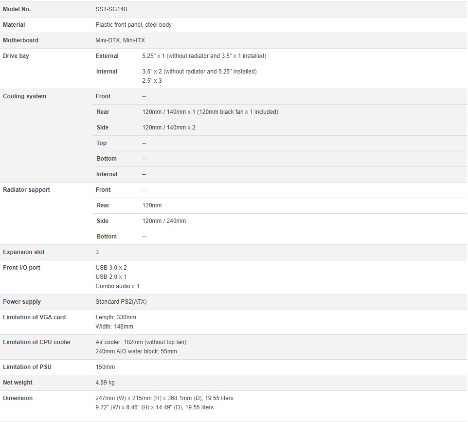
Specification
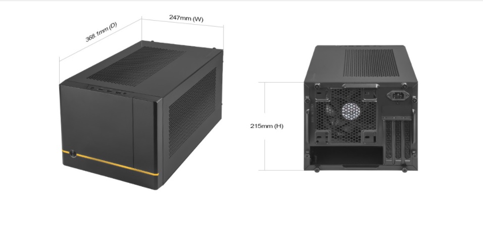
Dimension
Packaging and Unboxing
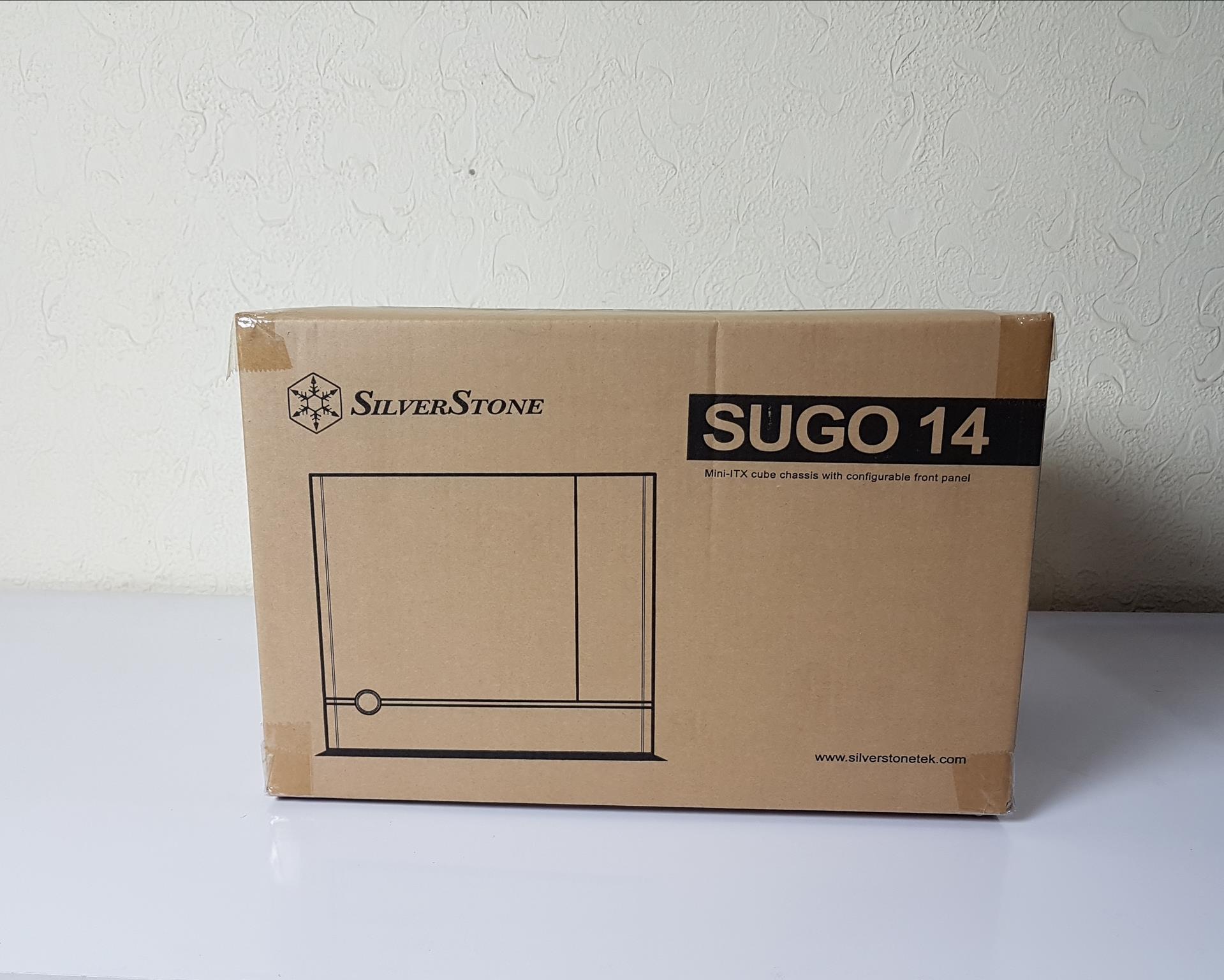
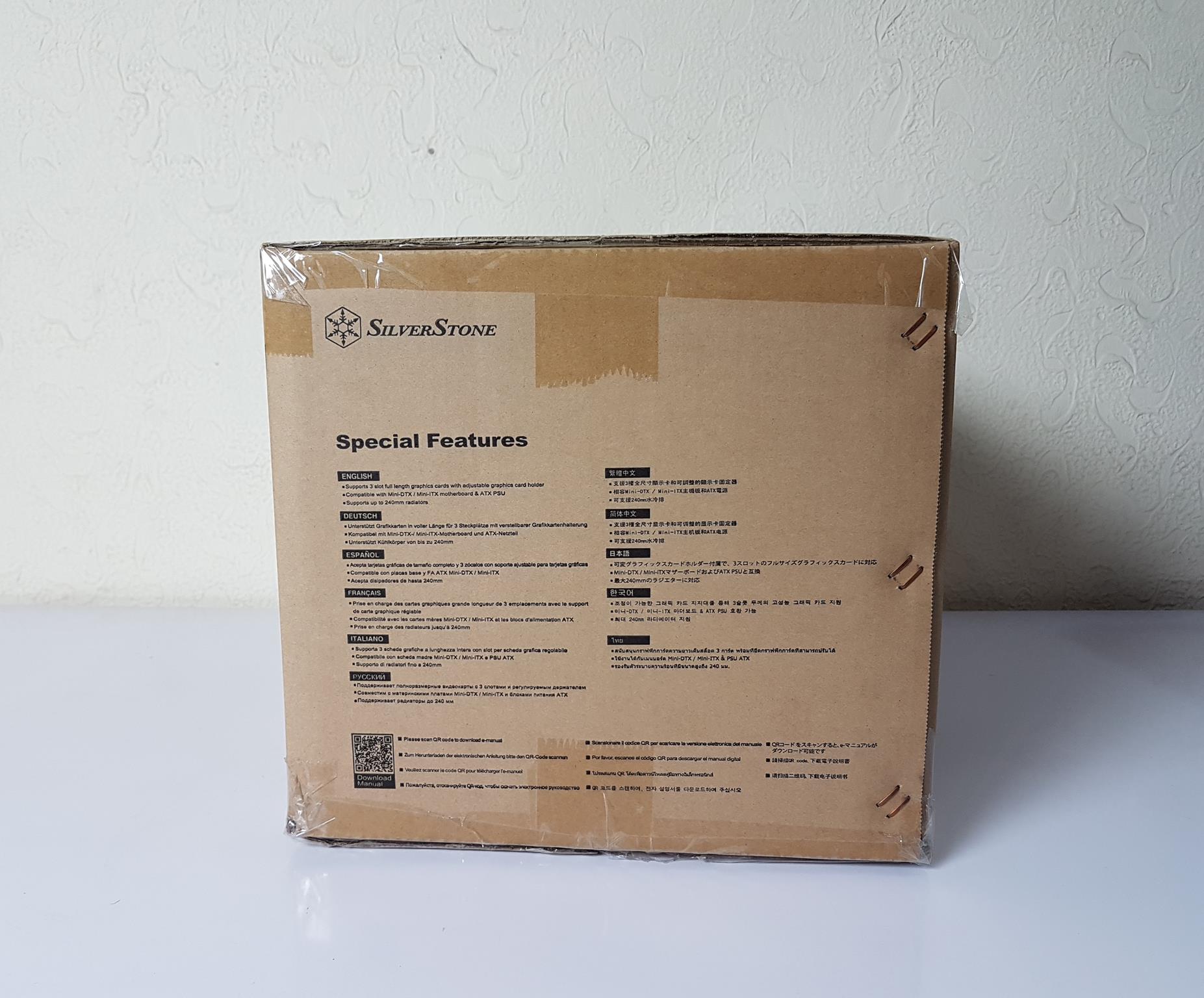
The chassis is shipped inside a cardboard box of brown color which is a standard for the chassis shipping.
The SUGO 14 is a mini ITX Cube chassis with a configurable front panel.
The SUGO 14 supports a 240mm radiator as well as a triple PCIe slot design to accommodate a thicker graphics card. It is designed around standard ATX PSU.
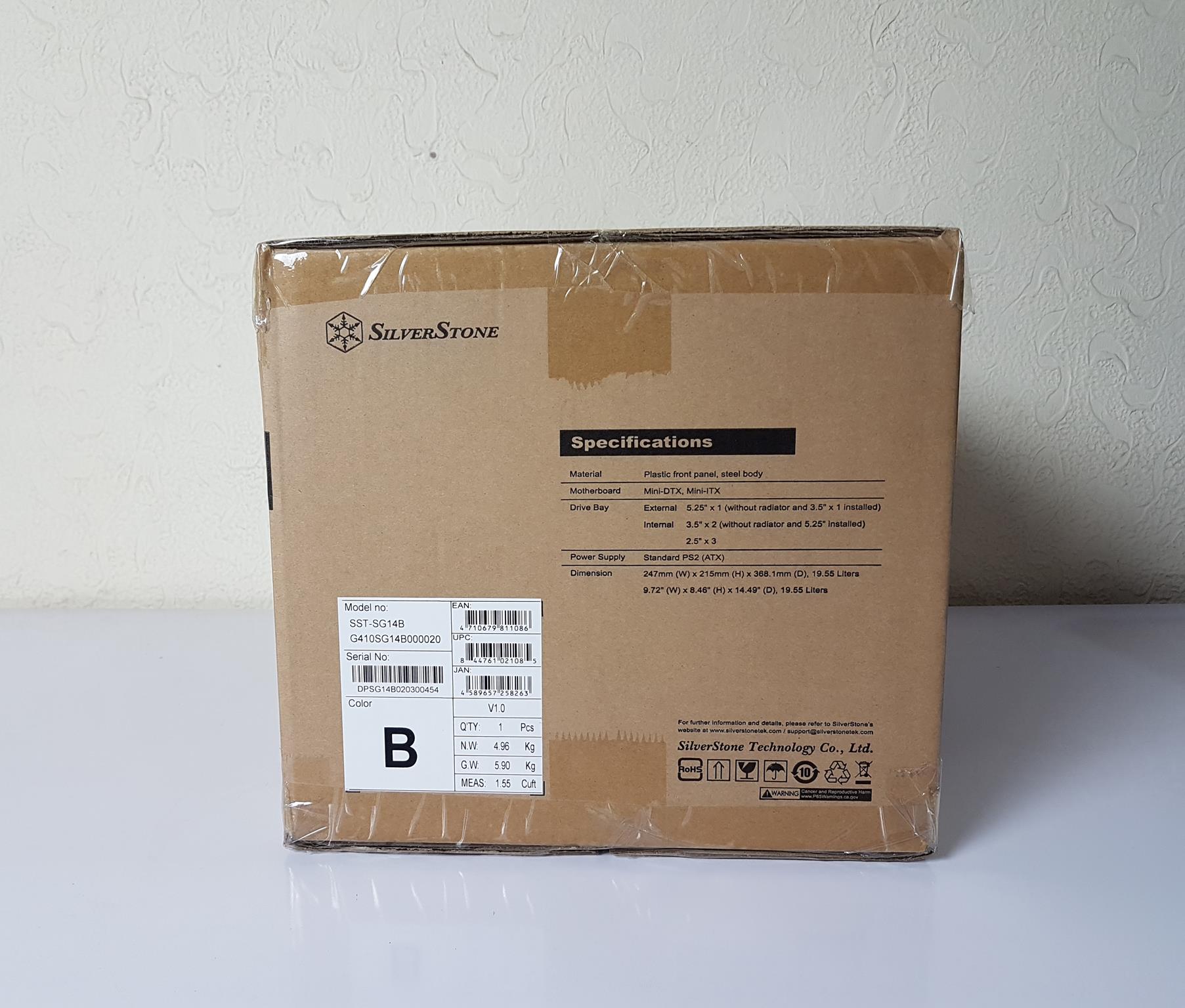
The specifications are printed. The overall volume of the chassis is 19.55 liters. The chassis also features a 5.25” bracket which is something we don’t see that often now these days.
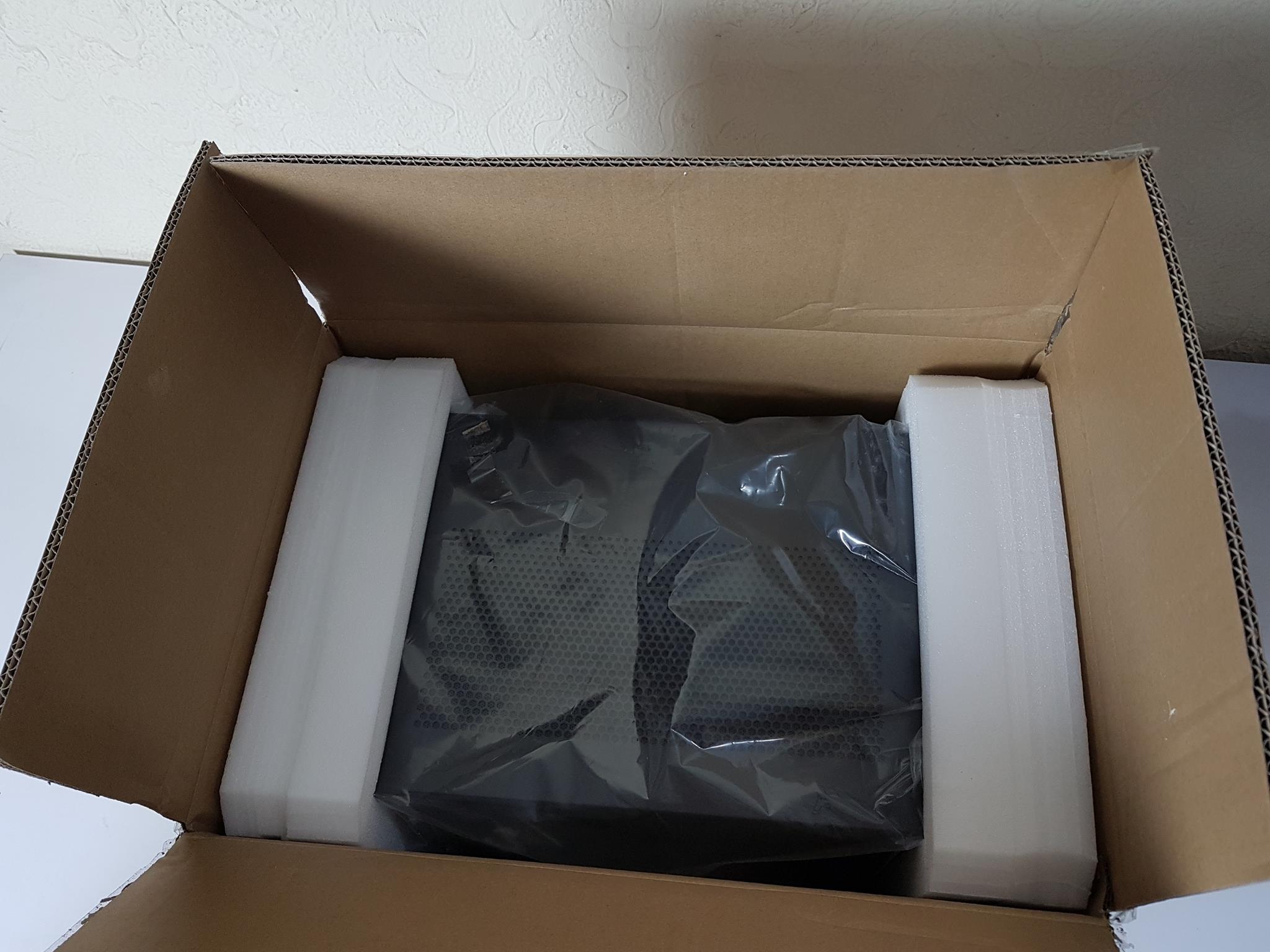
Opening the box will show the chassis tucked inside two white colors Styrofoam pads.
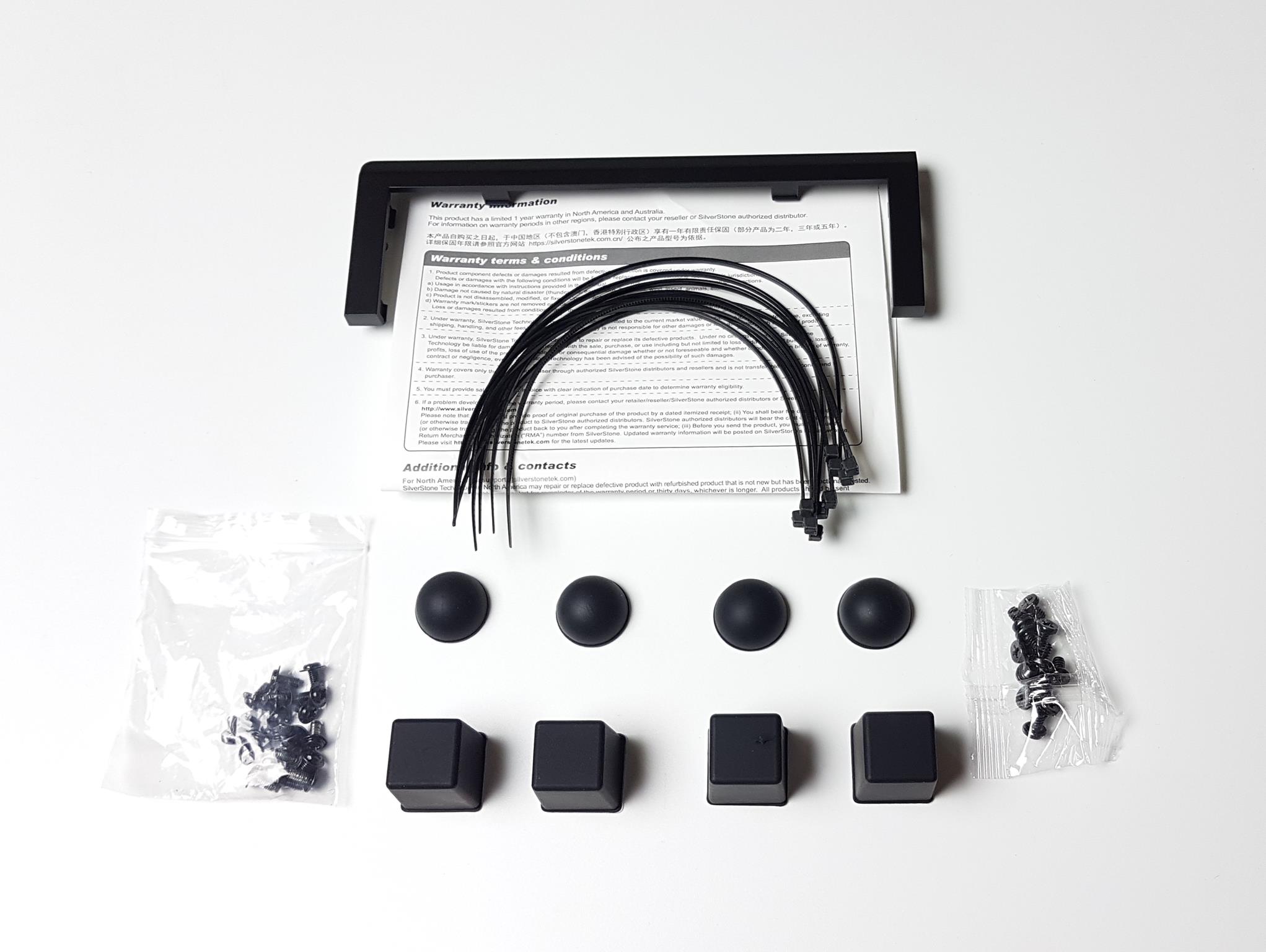
SilverStone has provided:
- 1x 5.25” Bracket cover
- Zip Ties
- Various Screws
- 4x Small Rounded Feet
- 4x Tall Feet
Closer Look
It is time to take a look at the chassis and see all the features. SUGO 14 is the new iteration in the SUOG lineup taking the design of SUGO 13 to the new level. There are many features that make this chassis stand out like support for a 240mm radiator, triple-slot for the thicker graphics card, CPU cooler support of up to 182mm height, standard PS2 PSU. These are the highlights of the chassis. Of course, there are considerations on the combination of the configurations and what is permissible in each configuration. We shall discuss all possible combinations. The SUGO 14 has a dimension of 247x215x368.1mm (WxHxD). 19.55 liters is the volume of the chassis. The chassis is made of a steel body except for the front panel which is plastic and is configurable. The net weight of the chassis is 4.89 Kg.
Exterior
Let’s start with taking a look at the exterior of the chassis.
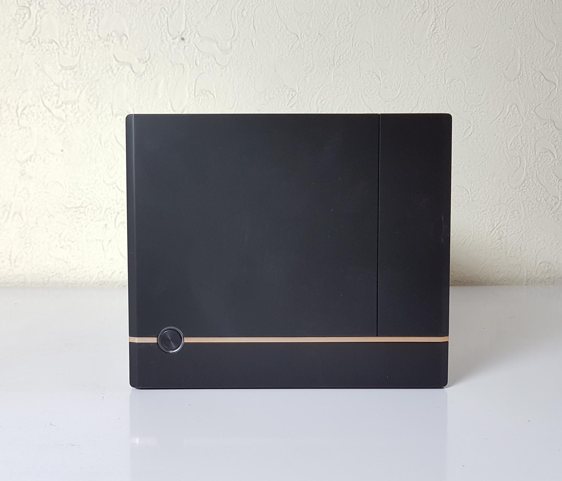
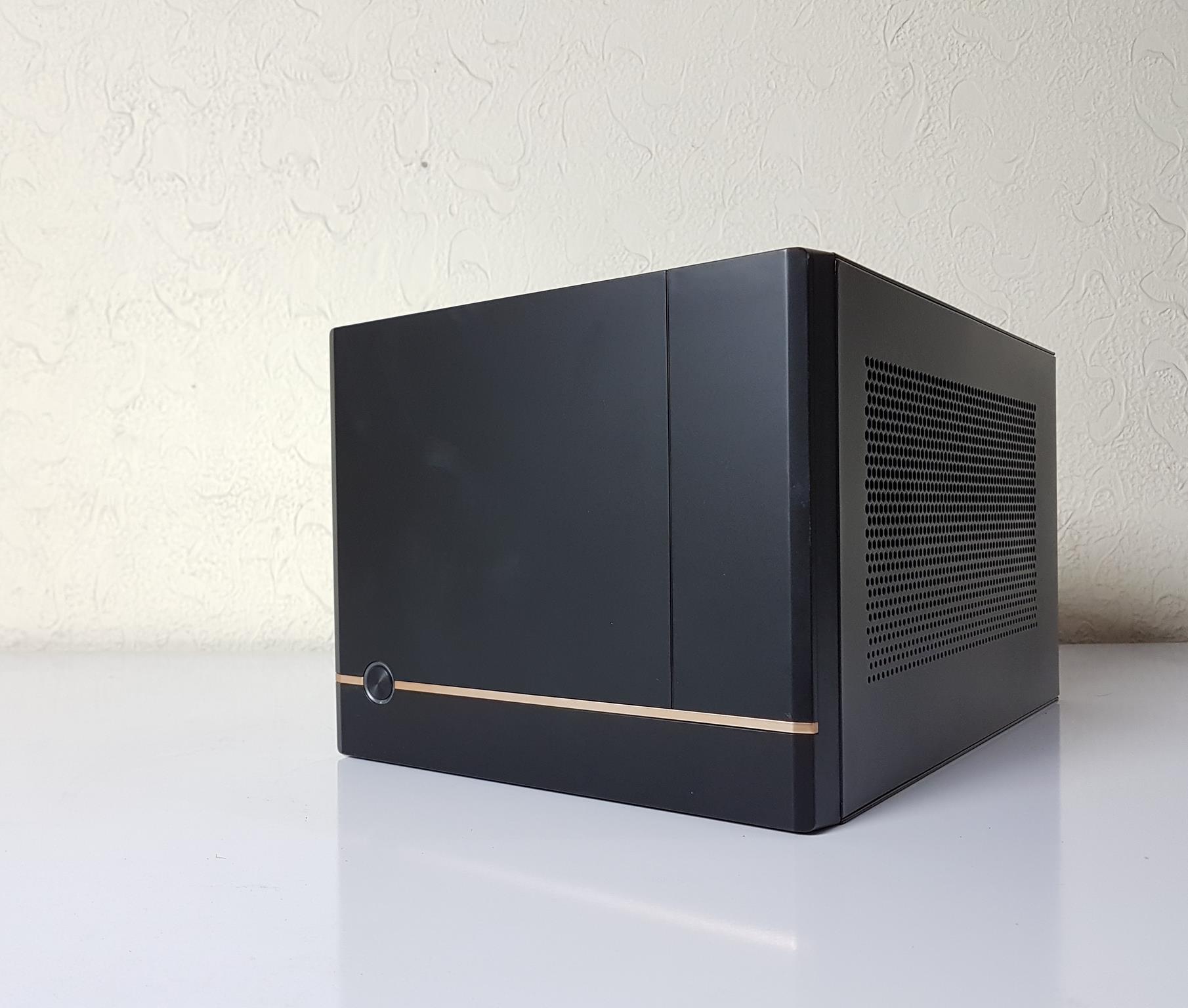
The SUGO 14 features a plastic made front panel. The front panel is a magnet for fingerprints so take care while handling. It has a simple yet beautiful layout. The right side portion is the entry mount for the 5.25” drives. If you will be using a 5.25” drive then this cover will be changed with the bundled 5.25” bracket. There is a zinc color lining towards the lower section which runs on the entire length of the frame. The power button on the left side and sit right on the zinc line. This creates one heck of a good look. How this panel is configurable?
- You can rotate the chassis with the power button side sitting on the bottom or place the chassis with the zinc line in a vertical layout.
- 5.25” drive bay mount
Further configuration options are on the inside of the front panel which we will look at shortly.
Here is another shot of the cross-section showing the front panel and the side of the chassis.
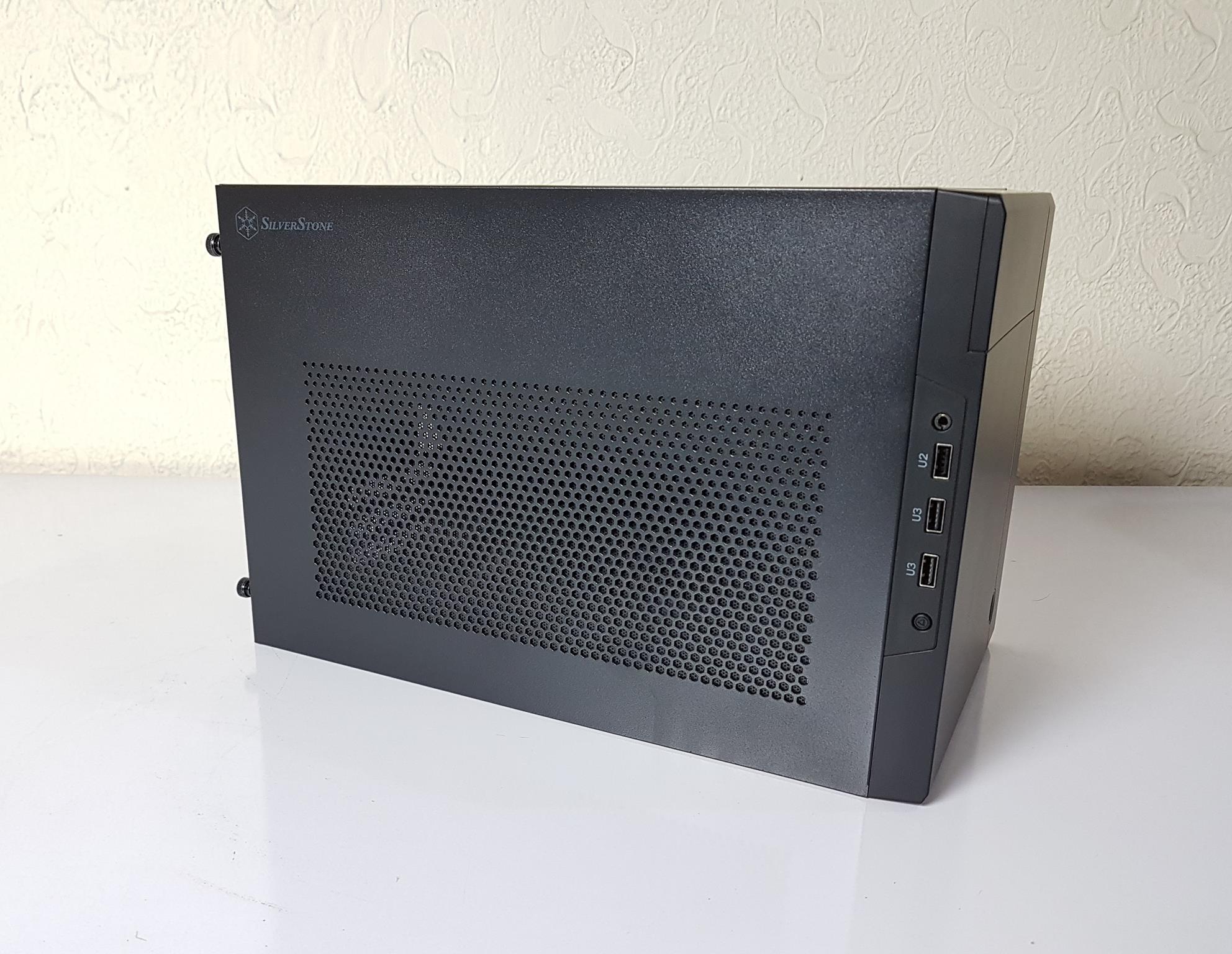
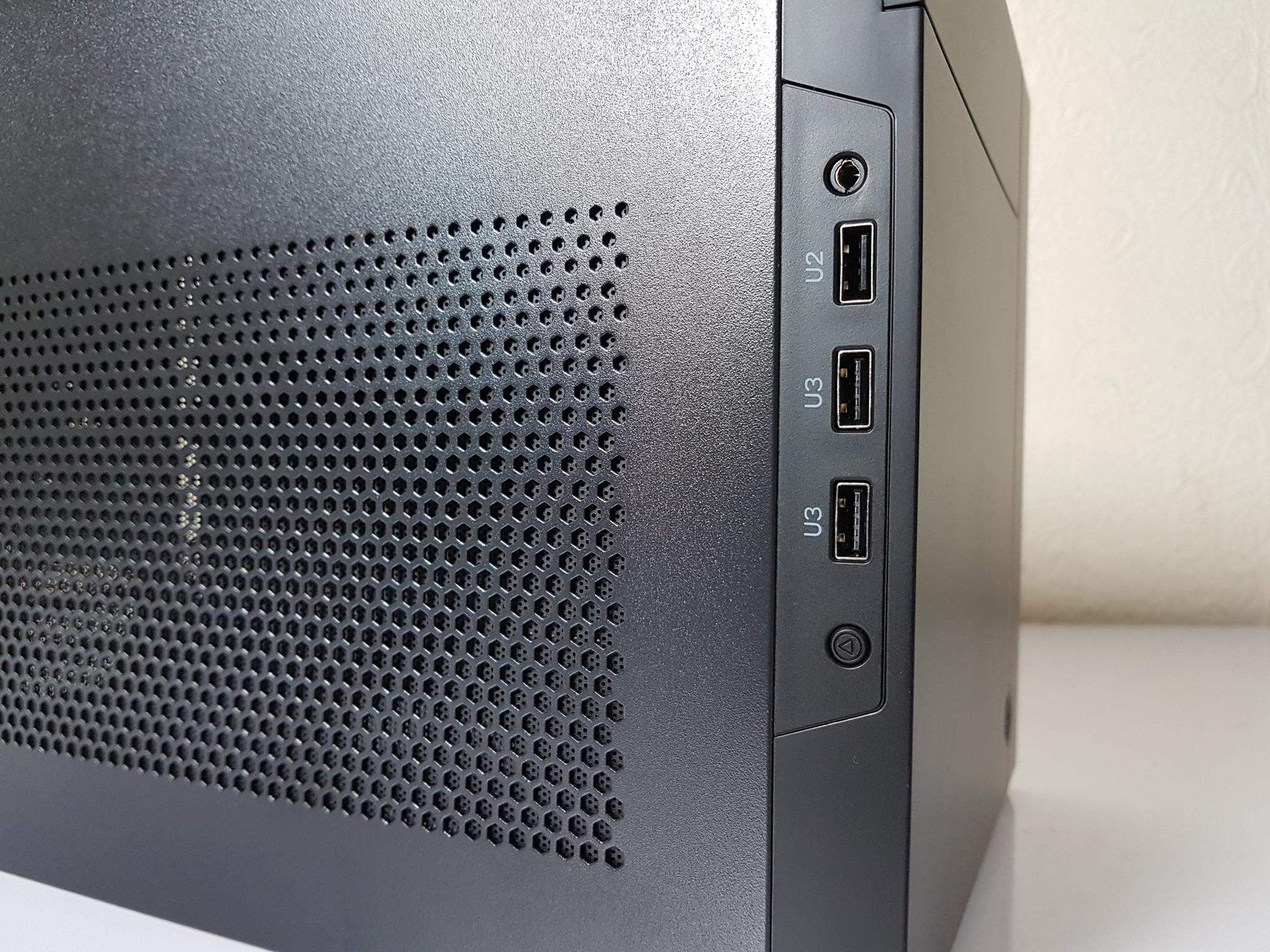
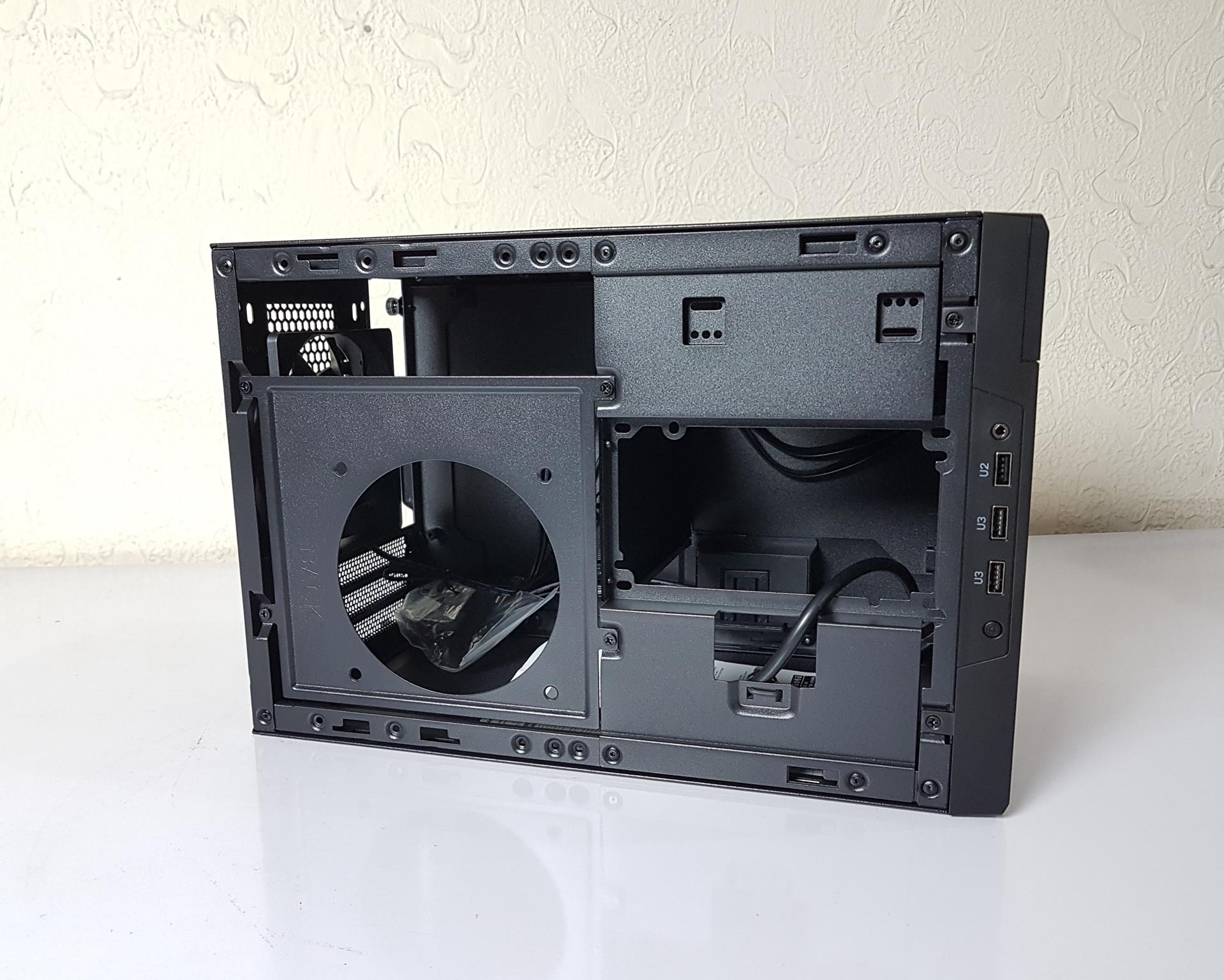
We have a solid panel with meshing on the lower section. There is a SilverStone logo on the upper left side. The I/O panel is on the rightmost side. The user has the option to either place the chassis in this configuration on the table or this side on the top. In our testing there is no thermal issue in both configurations.
The IO panel includes:
- 2 in 1 Audio Jack
- 1x USB 2.0 port
- 2x USB 3.0 ports
- Reset Button
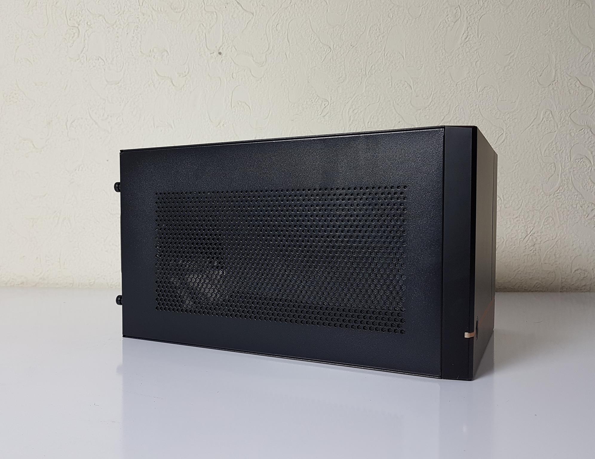
This is the right side of the chassis. This is where the mounting bracket is provided on the inside where a user can install a 240mm radiator or 3.5”/5.25” drives as permissible in the configuration. We again have a solid steel panel with the mesh.
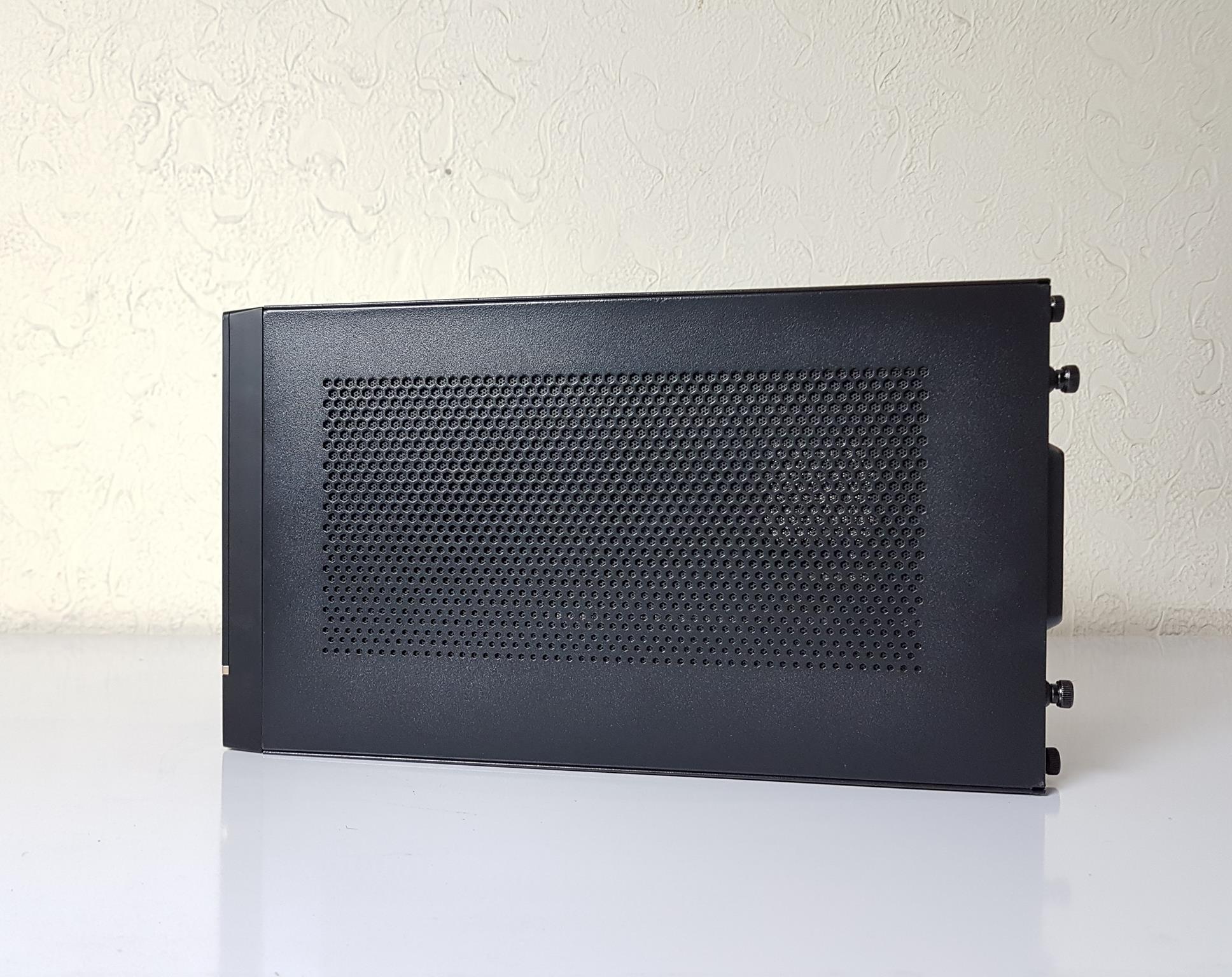
This is the left side of the chassis. It has a similar layout as is on the other side. We have a solid steel panel with mesh.
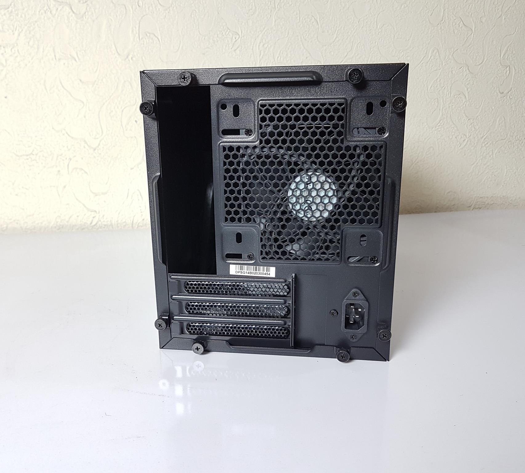
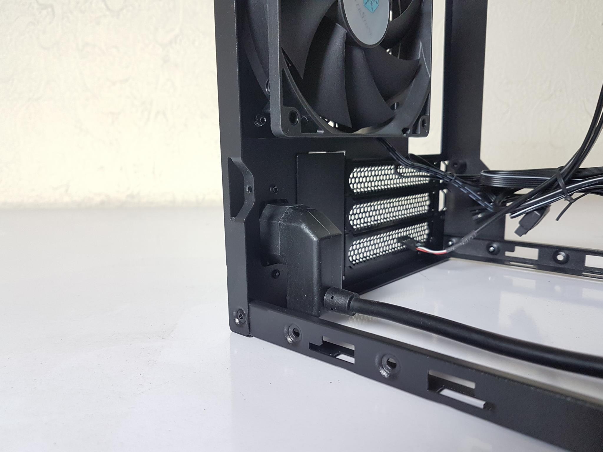
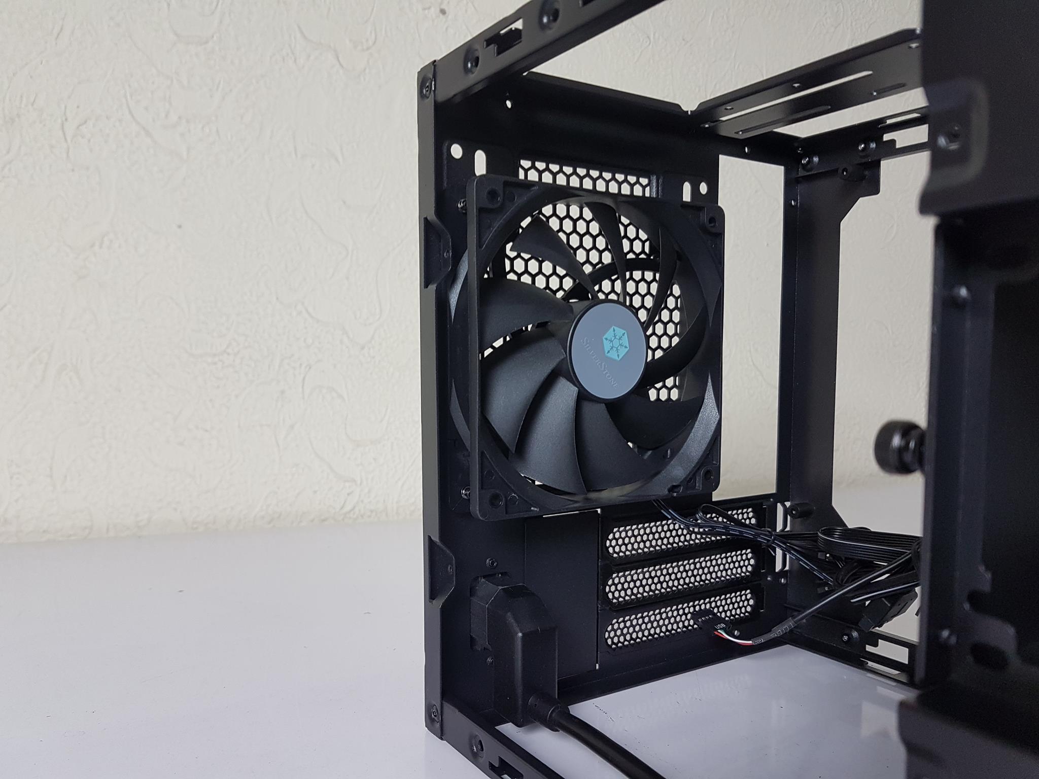
On the rear side of the chassis, we have a mount for 120mm or 140mm on the top. SilverStone has provided a 120mm black color fan on the rear. It was rotating at 1300 RPM as noted from the UEFI/BIOS. On the bottom left, we have triple PCIe slots. Each has a removable cover. A power port is provided on the right side. All four panels have captive thumbscrews which is a good design.
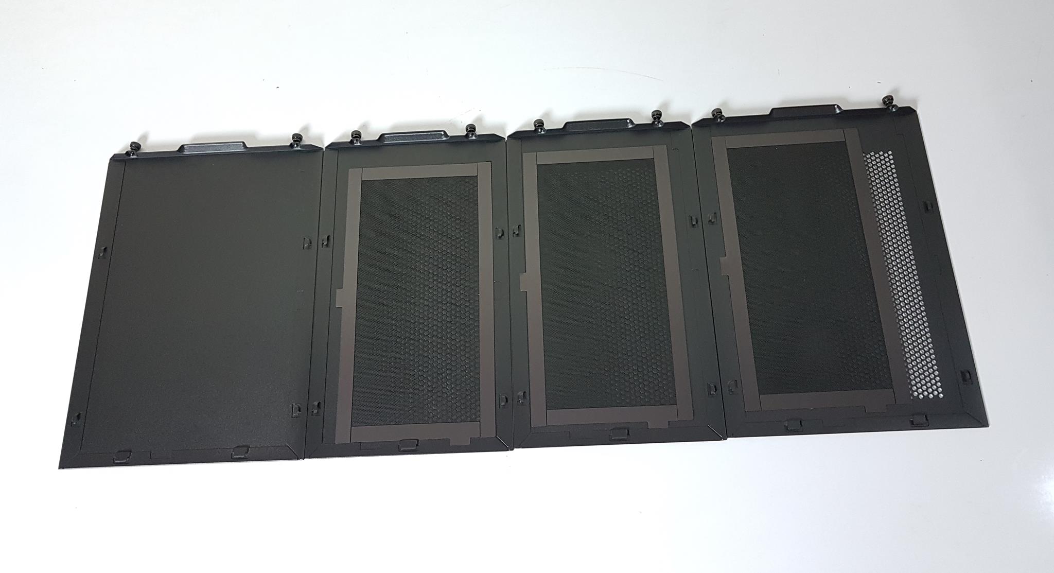
Before moving further, let’s take a look at all the panels from inside. Three panels have magnetic dust filters covering the mesh portions of the panels. One panel is solid design without any perforation. This panel sits on the bottom of the chassis.
Interior
It is time to take a look at the inside of the chassis.
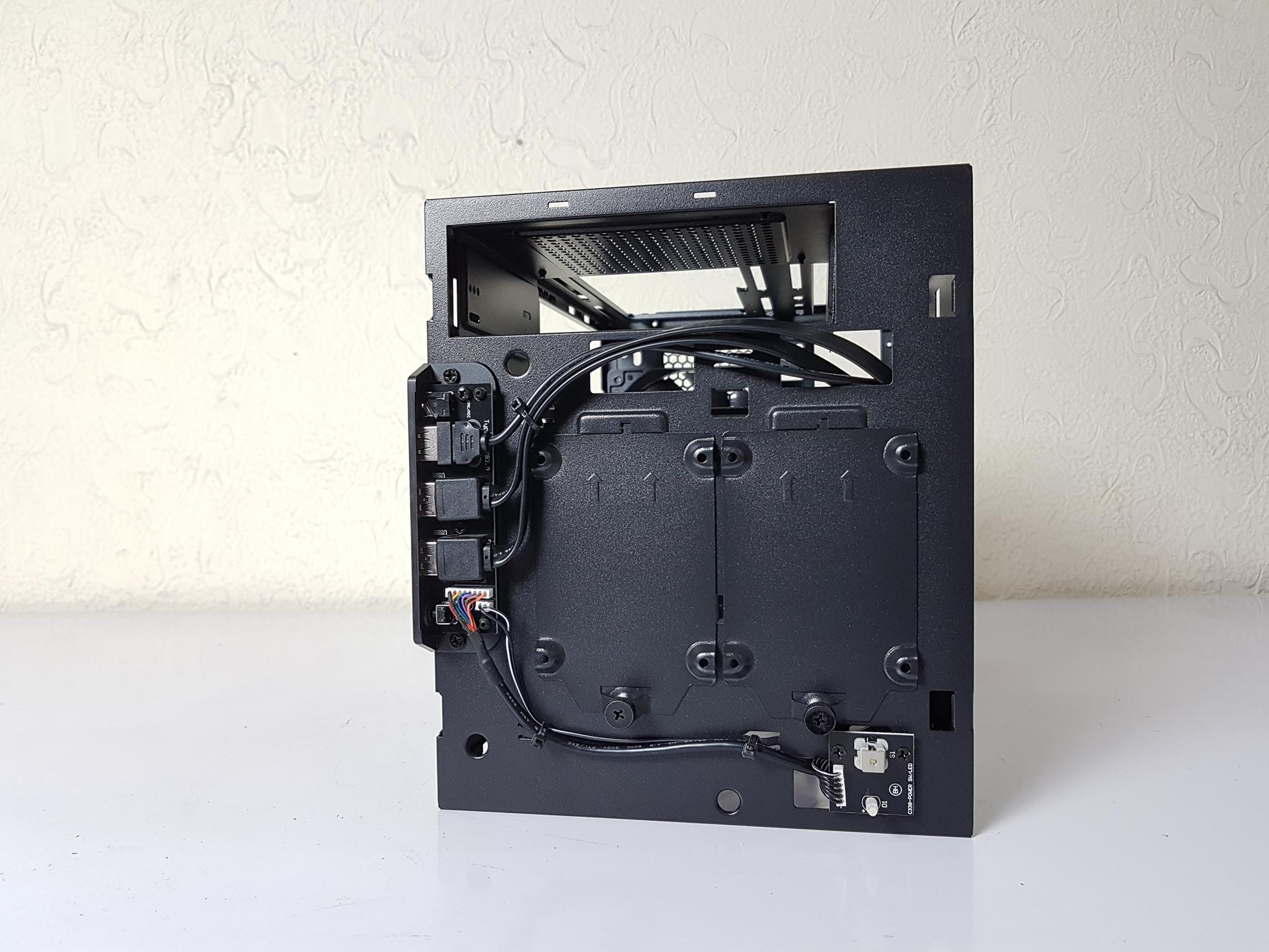
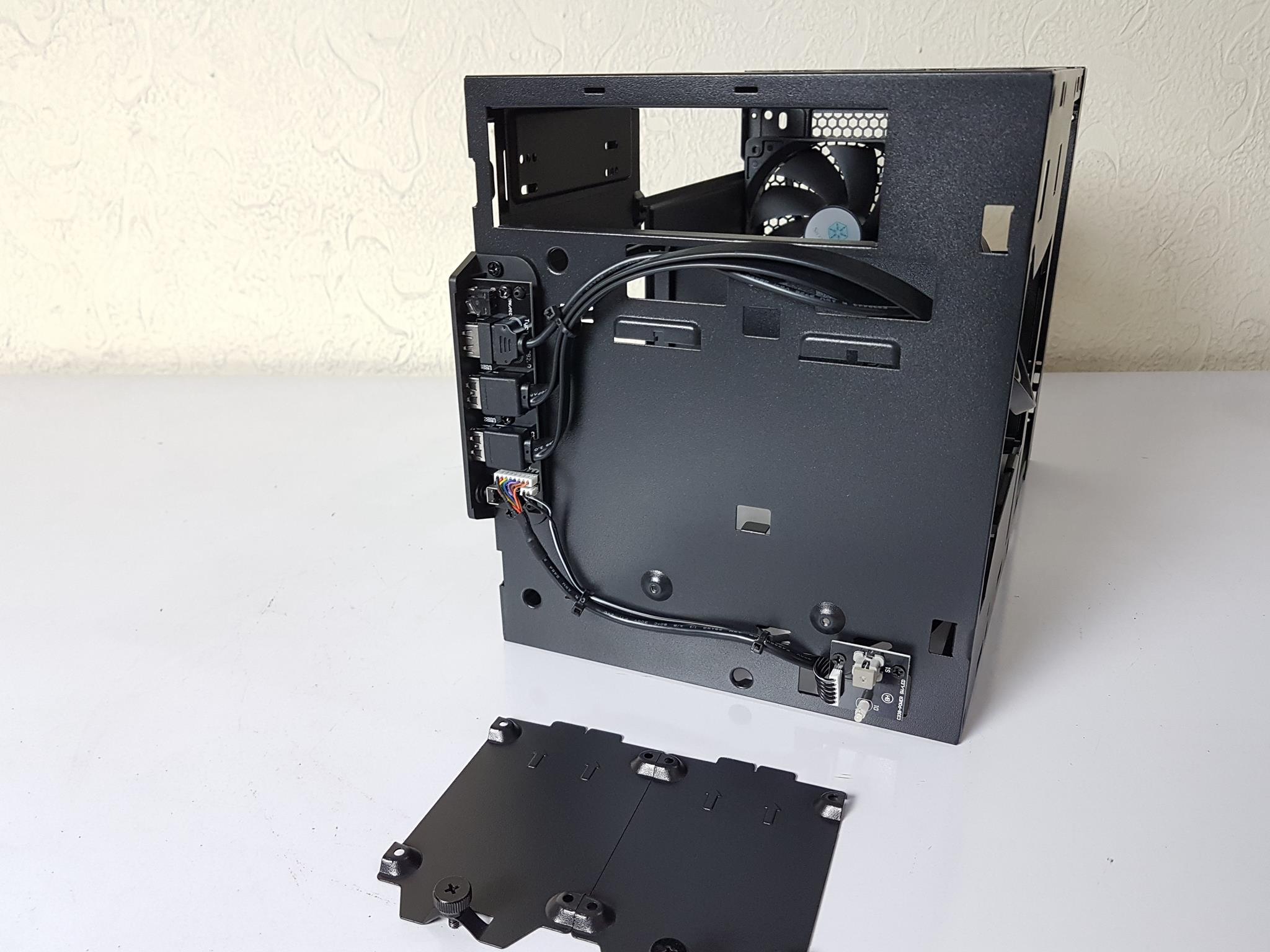
Taking the front panel off, we get to see two 2.5” drive brackets. These brackets have captive thumbscrews. Kudos to their design team for such an attention to the detail. We have two cutouts right on the top of these brackets. This is where the cables are routed through. We have a 5.25” drive bay cutout on the top left side. The cabling of the I/O panel are well laid out so is the cable going from the power button CB to the I/O panel.
The above picture shows the front side with 2.5” drive brackets removed.
The above picture shows the inner side of the front panel.
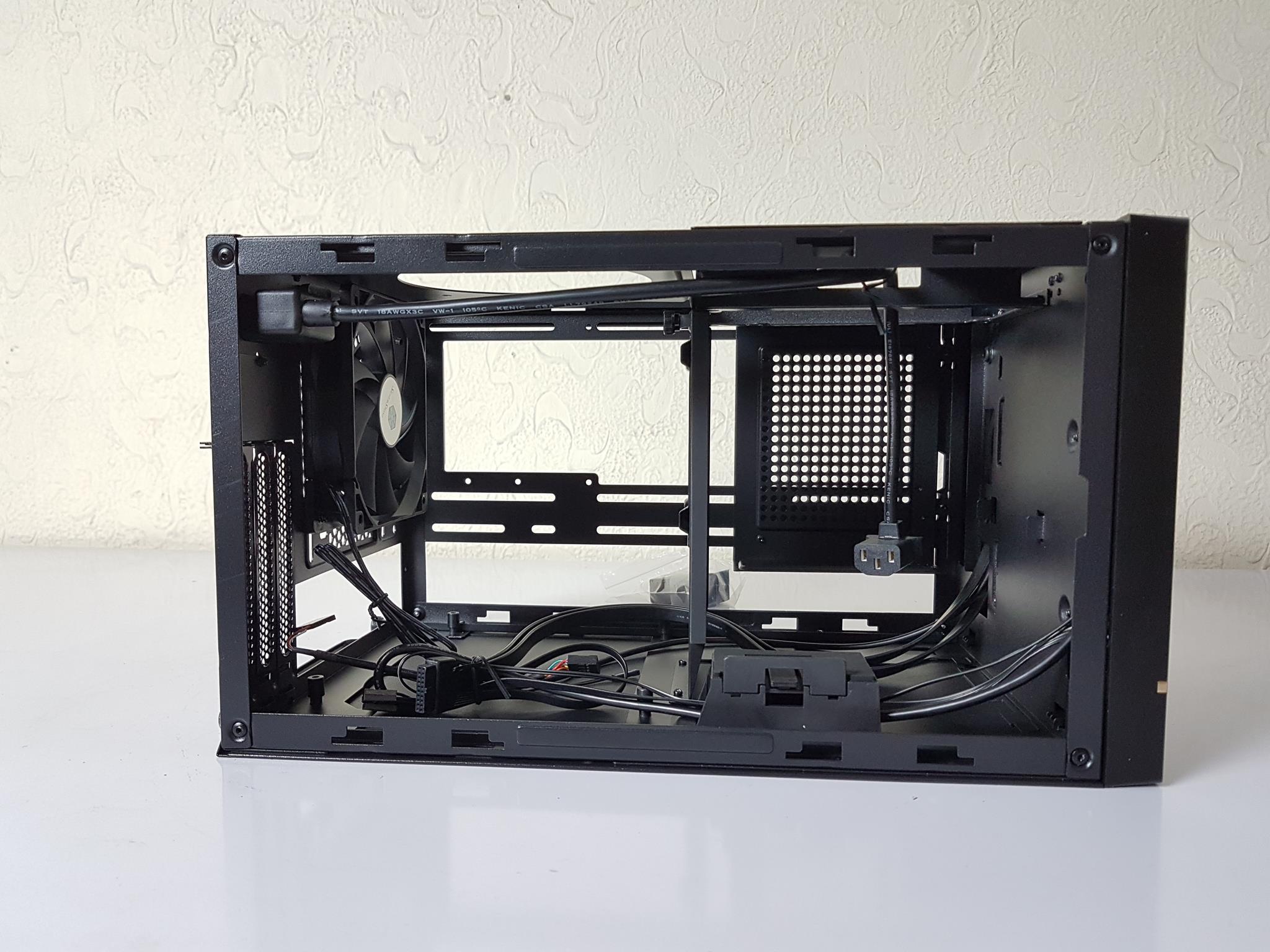
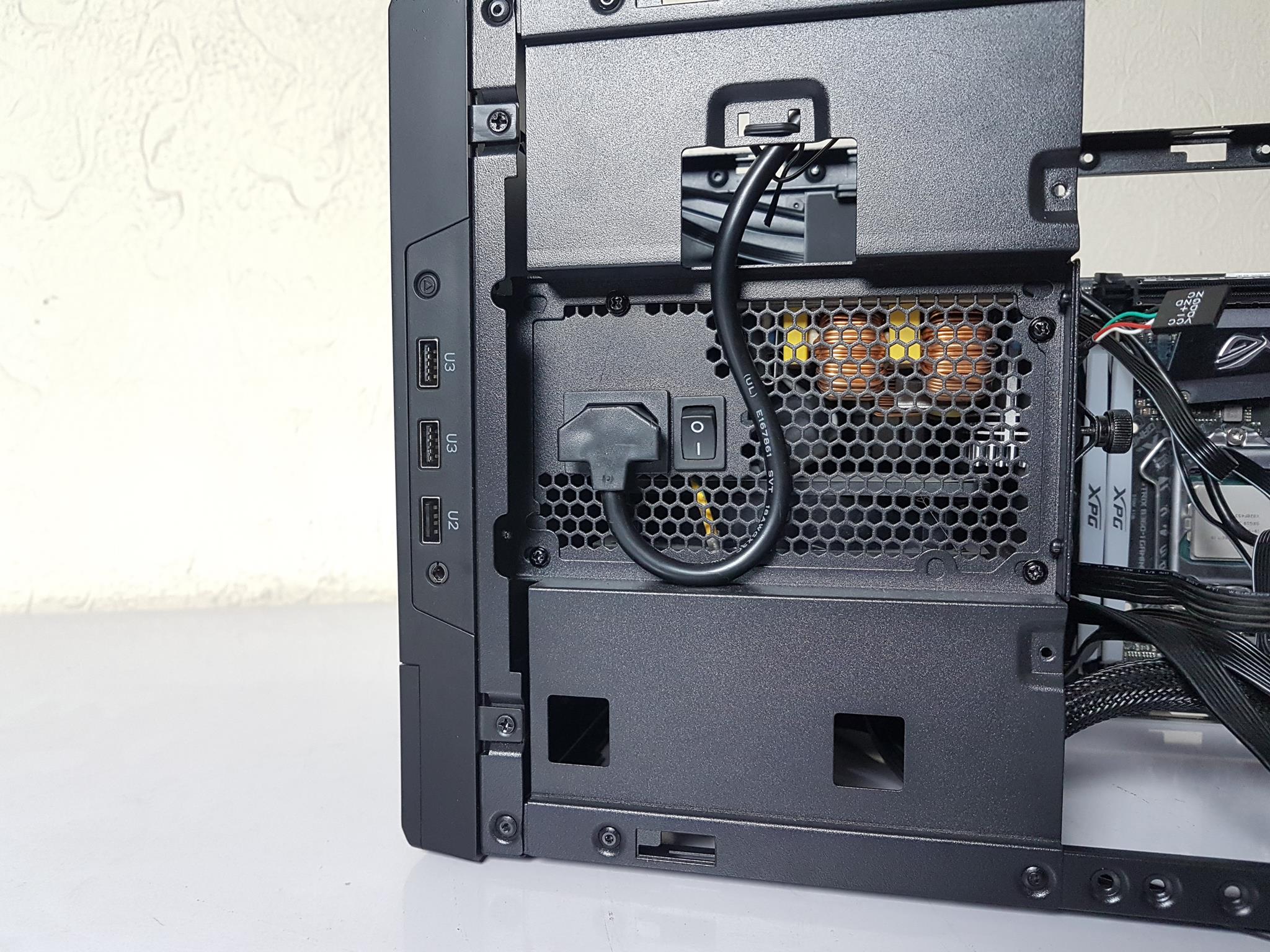
Taking a look at the side, there is a cover (fan bracket) on the left side where 120mm fan can be installed. This is the top side and the fan is recommended to be installed as exhaust. The top cover is removable. We have fixed structures on the right side. There is an opening in the middle. This is where the PSU is secured using screws 4x screws. There is a power cord running from the rear to this side (will show that in detail shortly). That cord is to be connected to the PSU. There is a cutout on the lower section from where the power cord is routed upward.
This is the top view of the side.
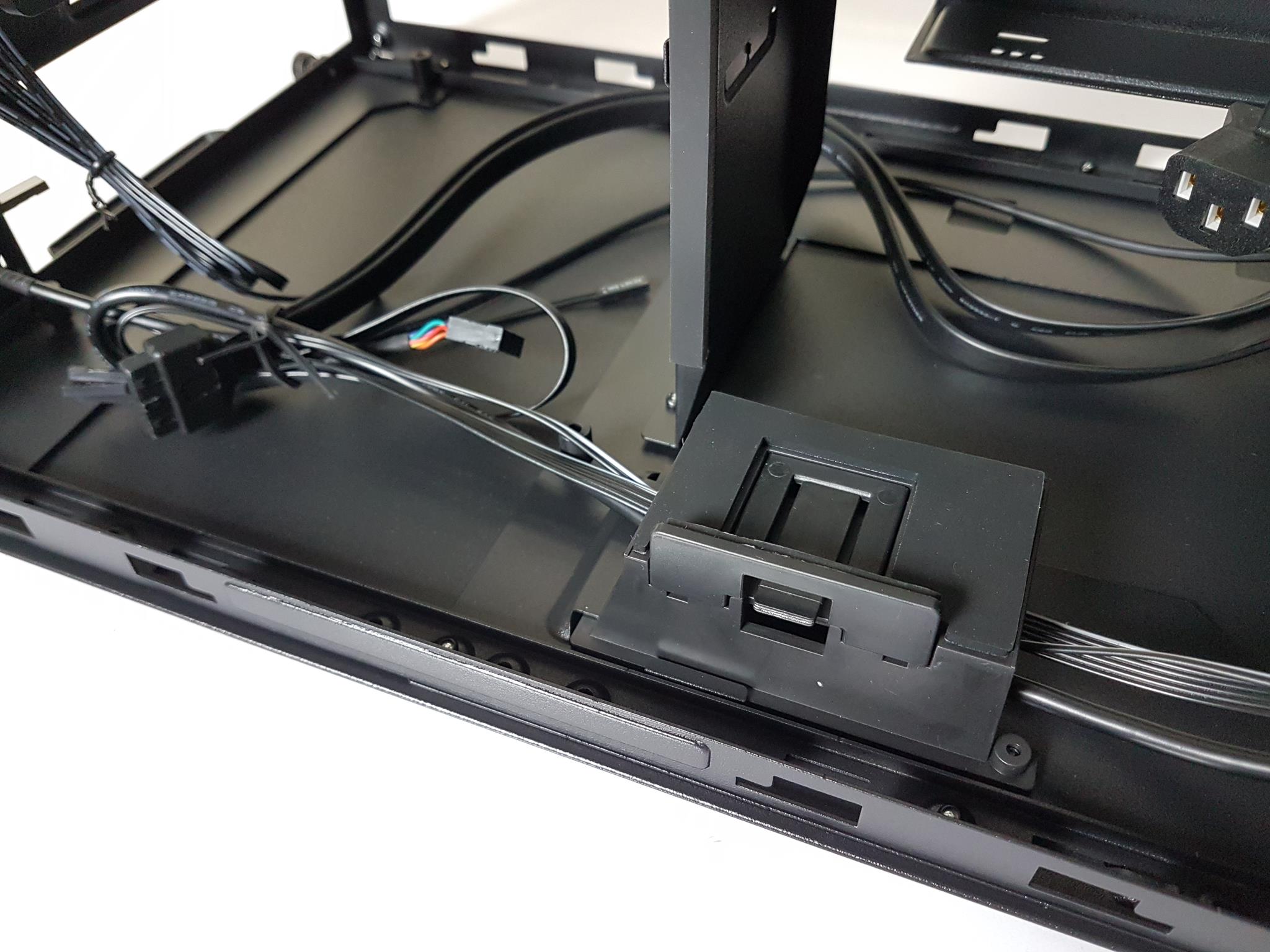
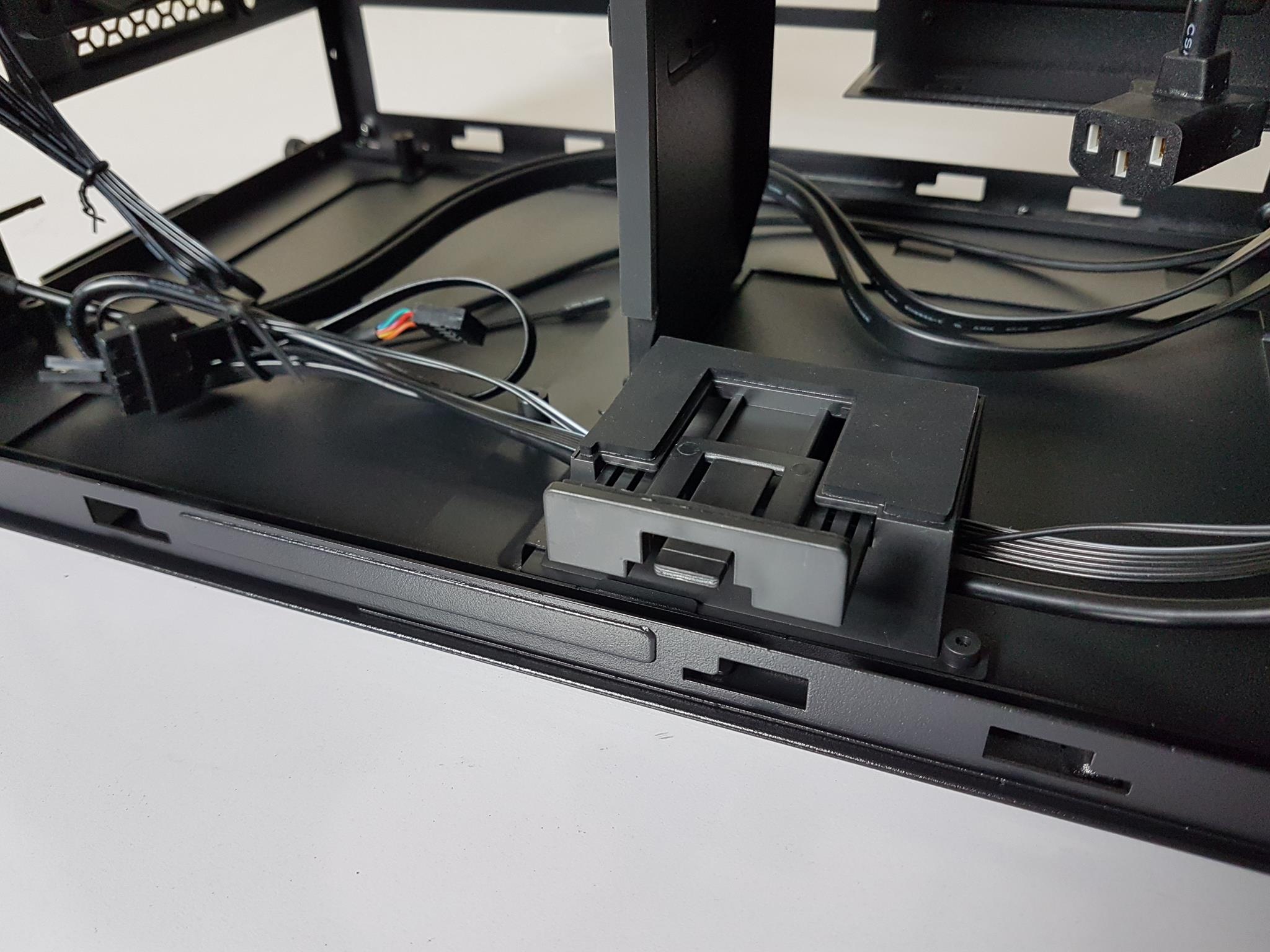
This is the power cord. It is already connected to the power port on the rear of the chassis and it is running on the inside towards the back of the PSU mount as shown in the second last picture above.
The above picture is showing the layout with the fan bracket removed. Here the power cord is also clearly visible on the bottom rack.
There is a 120mm all black fan pre-installed on the rear of the chassis. The maximum speed noted was 1300 RPM from the UEFI/BIOS. It has 9 blades and there is a silver color SilverStone logo in the middle. The fan is powered by a 3-pin connector cable.
There is another 2.5” drive bracket on the inner side of chassis. This bracket is facing the rear 120mm fan. It also has a captive thumbscrew. This is the bracket which I have used to mount a 2.5” SSD for the testing.
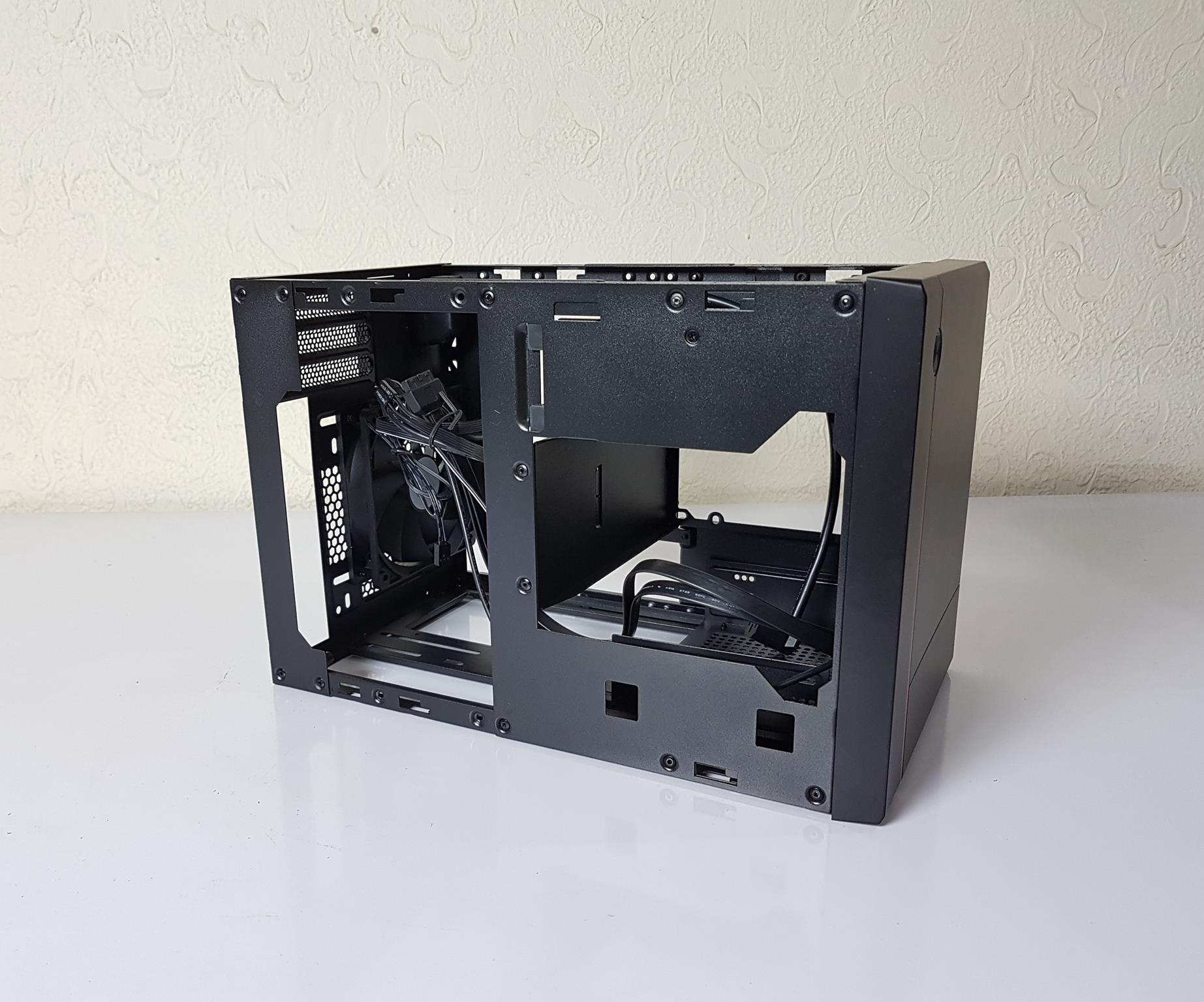
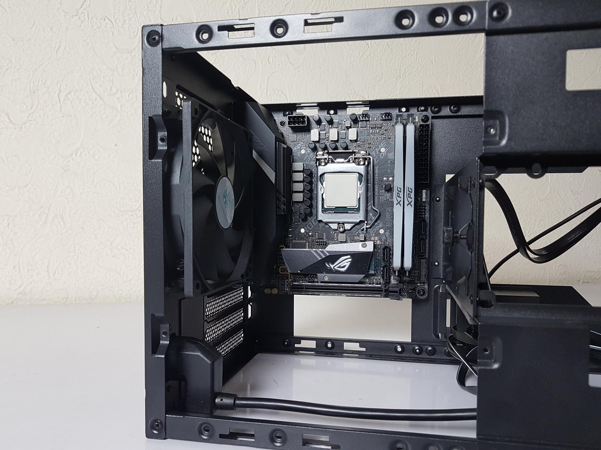
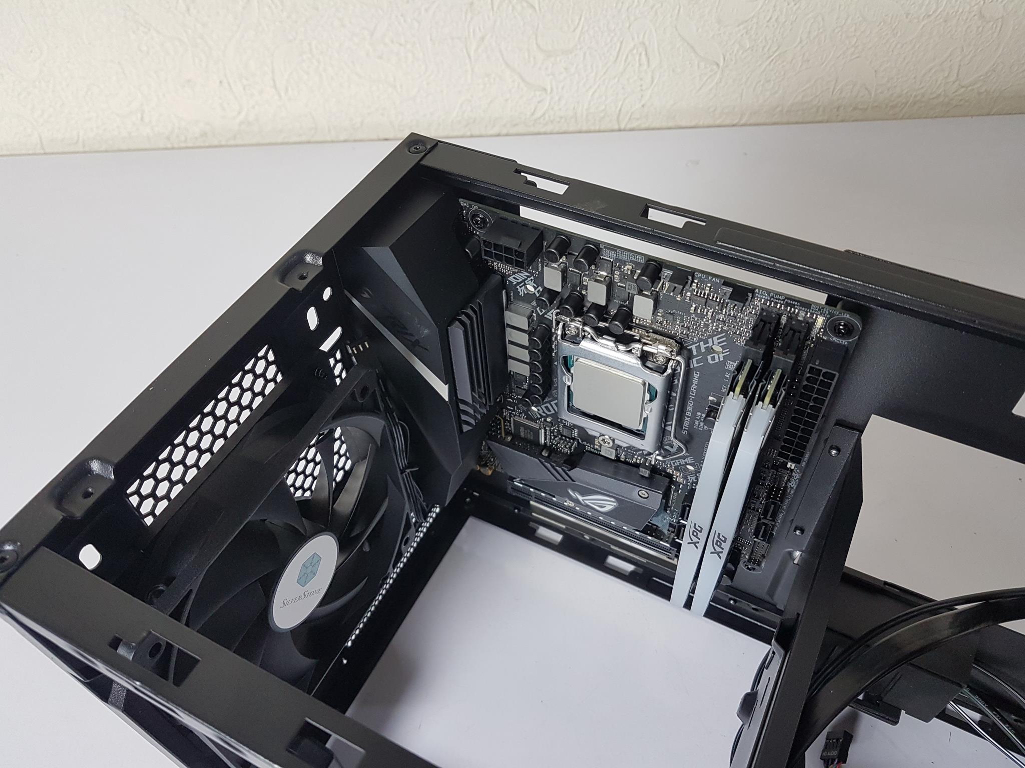
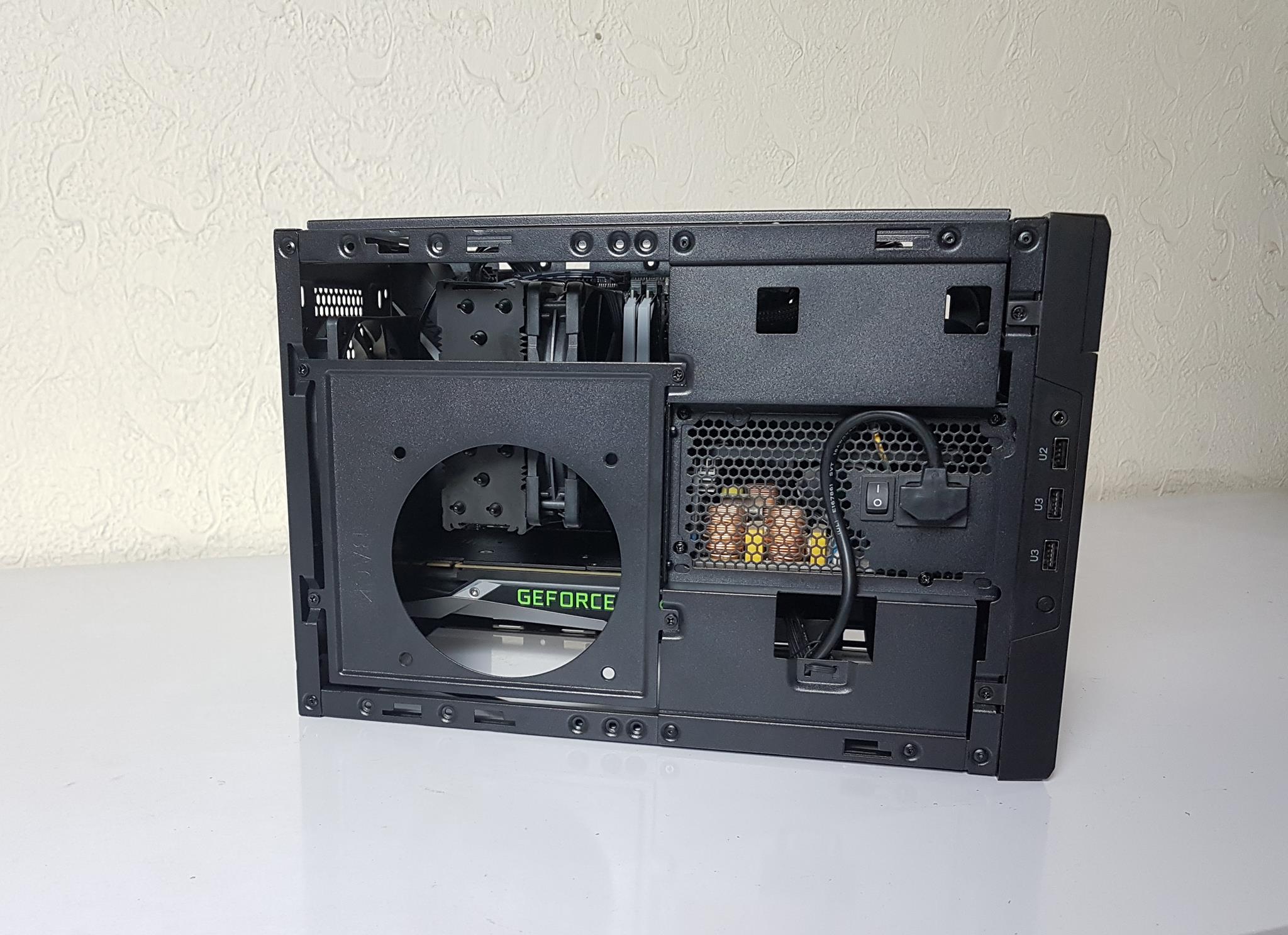
Let’s take a look at the other side of the chassis. We have an open layout here. There are 4x black color standoffs on the left side on the bottom. This is where the motherboard is installed. If you were to place the chassis with this side facing you on the table then the graphics card will be in vertical layout. During our testing, placing the chassis upward or downward, we did not see any thermal impact on the graphics card. The graphics card permissible length is 330mm with a width of 148mm.
There is a graphics card holder, almost in the middle. Pull out its tab before installing the graphics card.
The above picture is showing the pulled tab on the graphics cardholder.
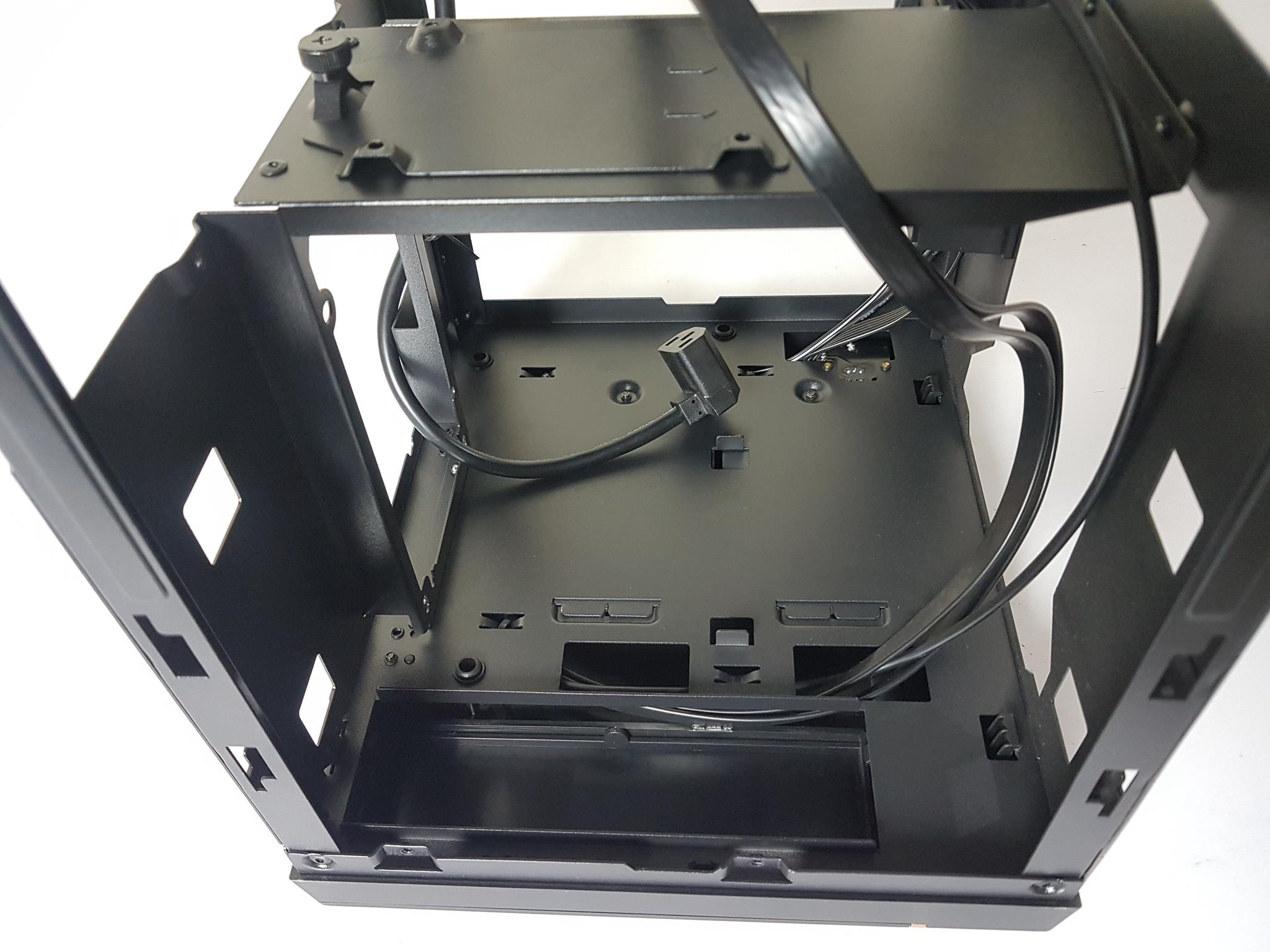
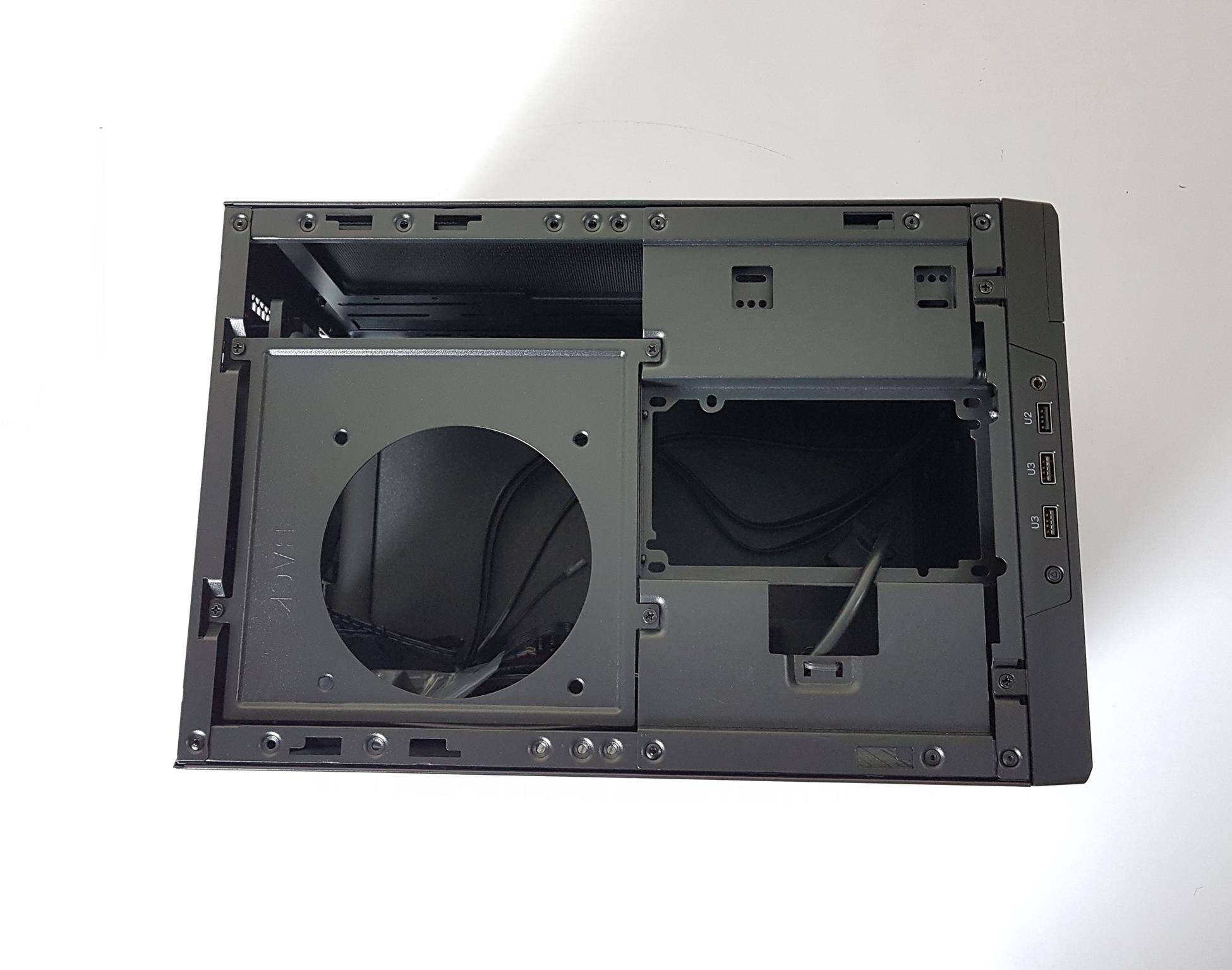
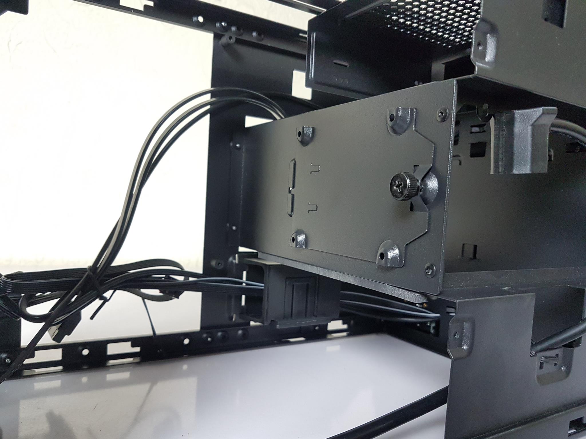
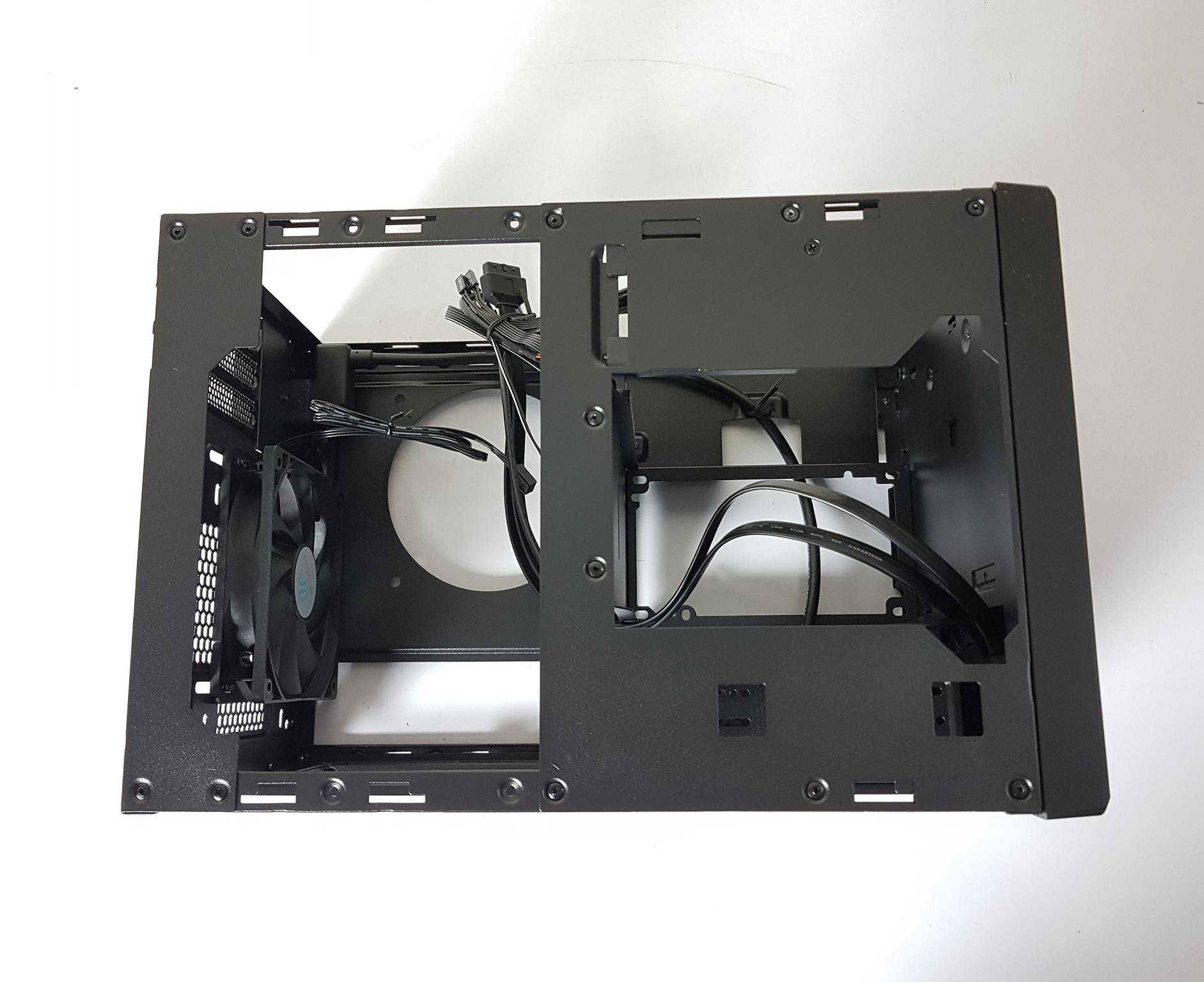
This is the bottom side. On the left side the motherboard is to be installed. There is a fixed structure on the right side with a cutout in the middle. The PSU is slided in through this cutout. There are channels or rails to guide the PSU when moving in.
This is the top view of the side for better understanding.
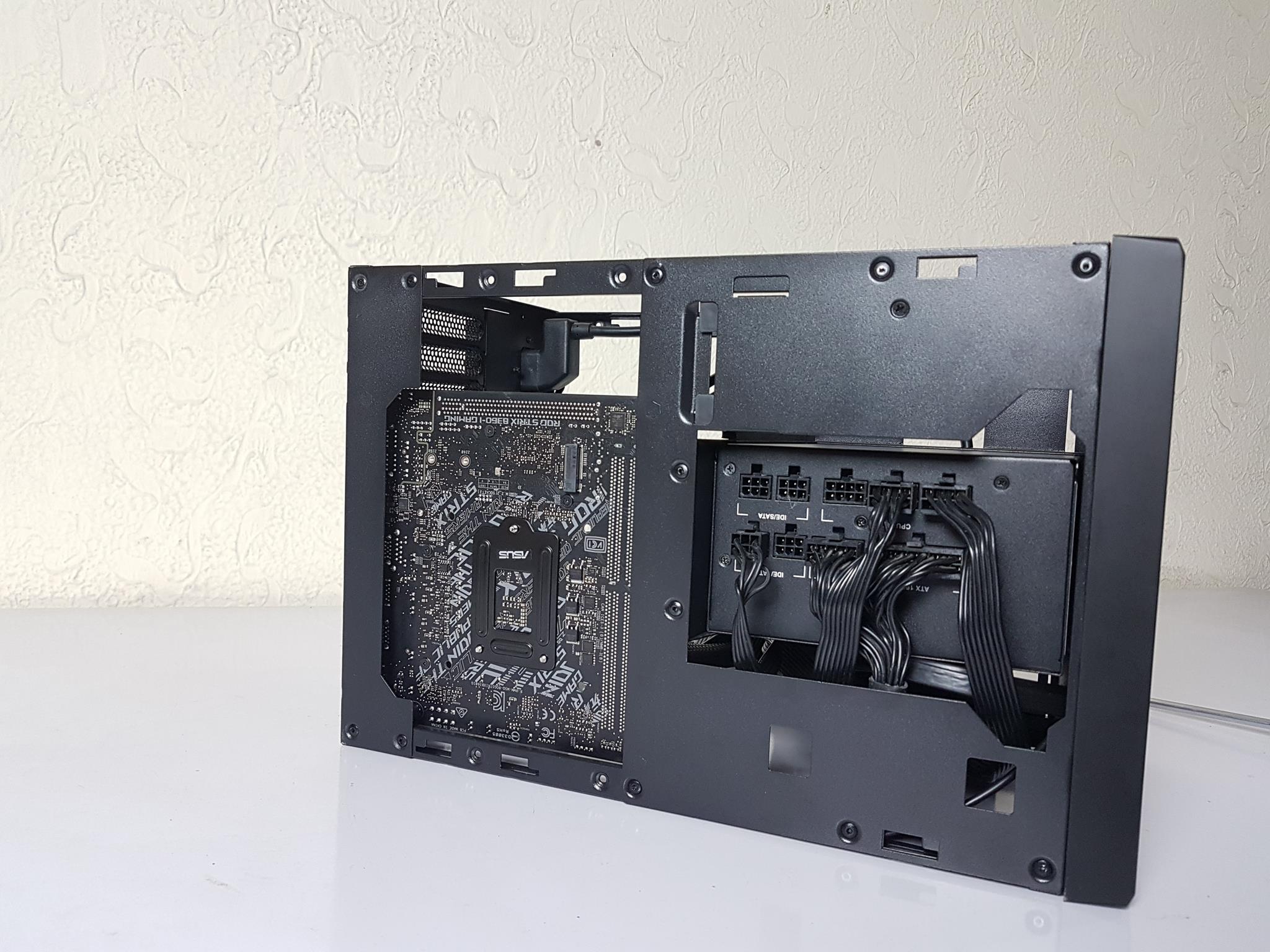
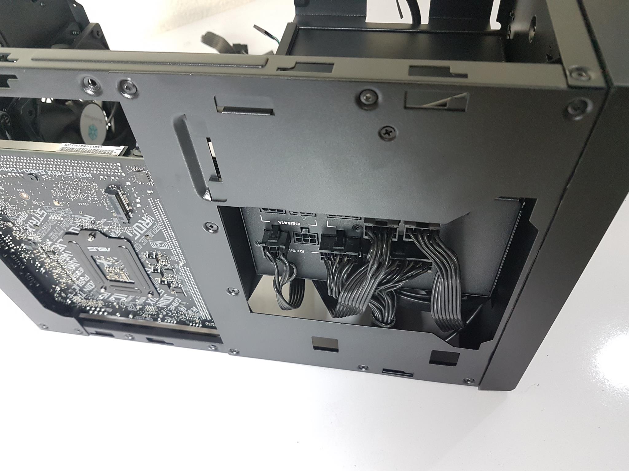
I am showing this picture to illustrate some points for this side:
- There is enough space on the back of the motherboard to install the M.2 SSD.
- There is enough space on the back of the PSU to pass or tuck the cables around. This will also depend upon the type of the cables. Flat cables are easier to manage than then the carbon sleeved ones.
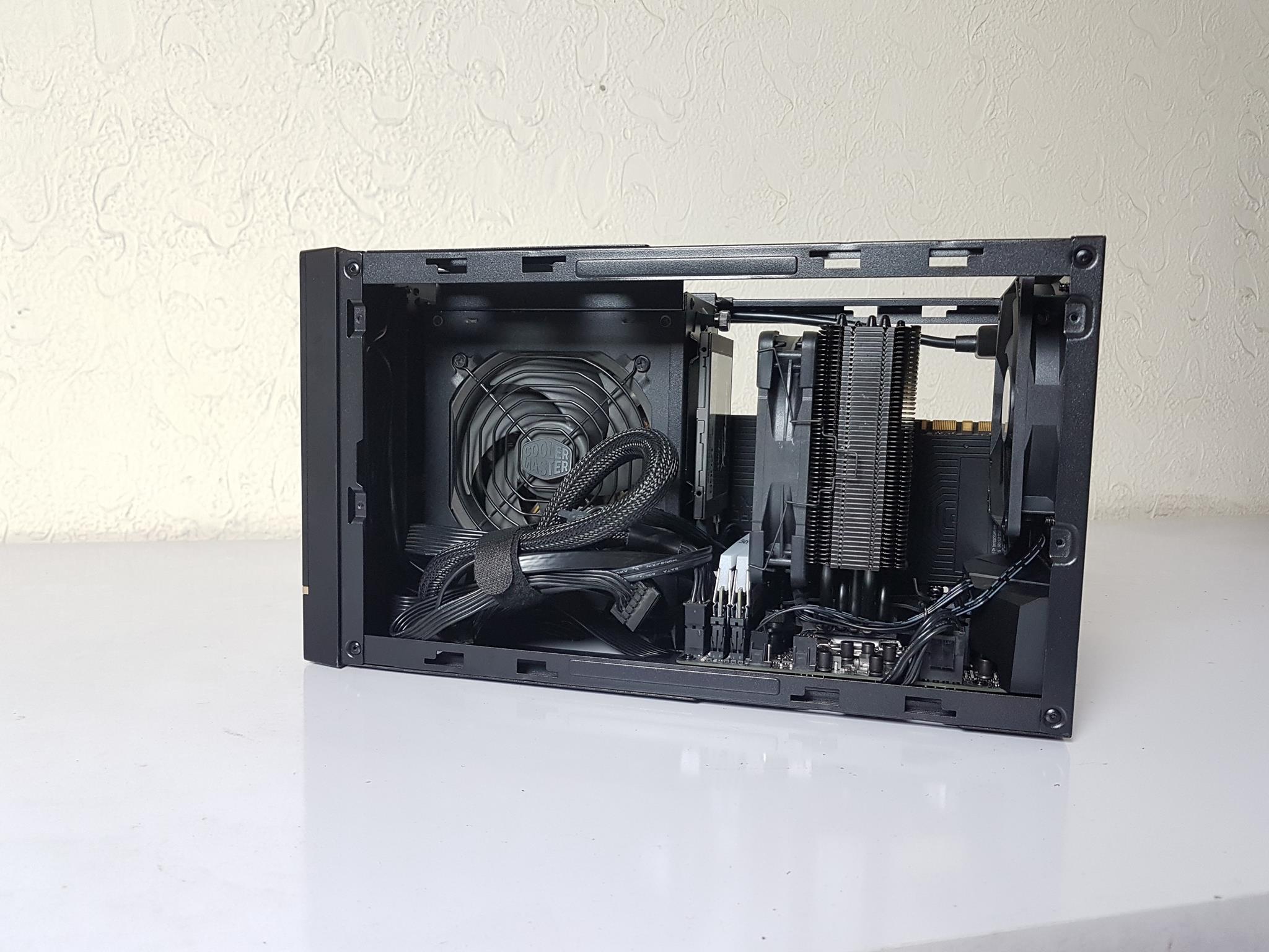
The PSU area is spacious enough for cable management.
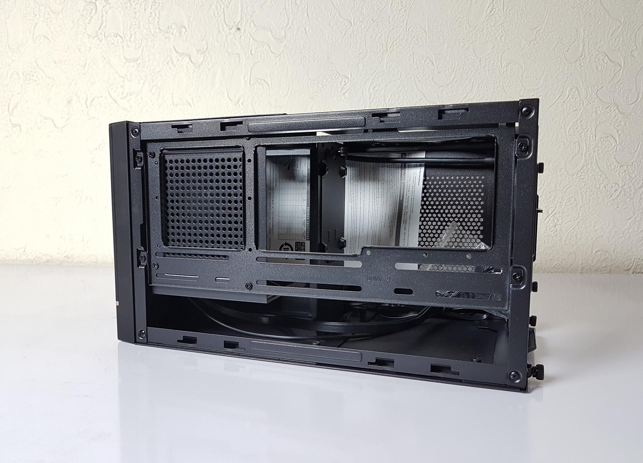
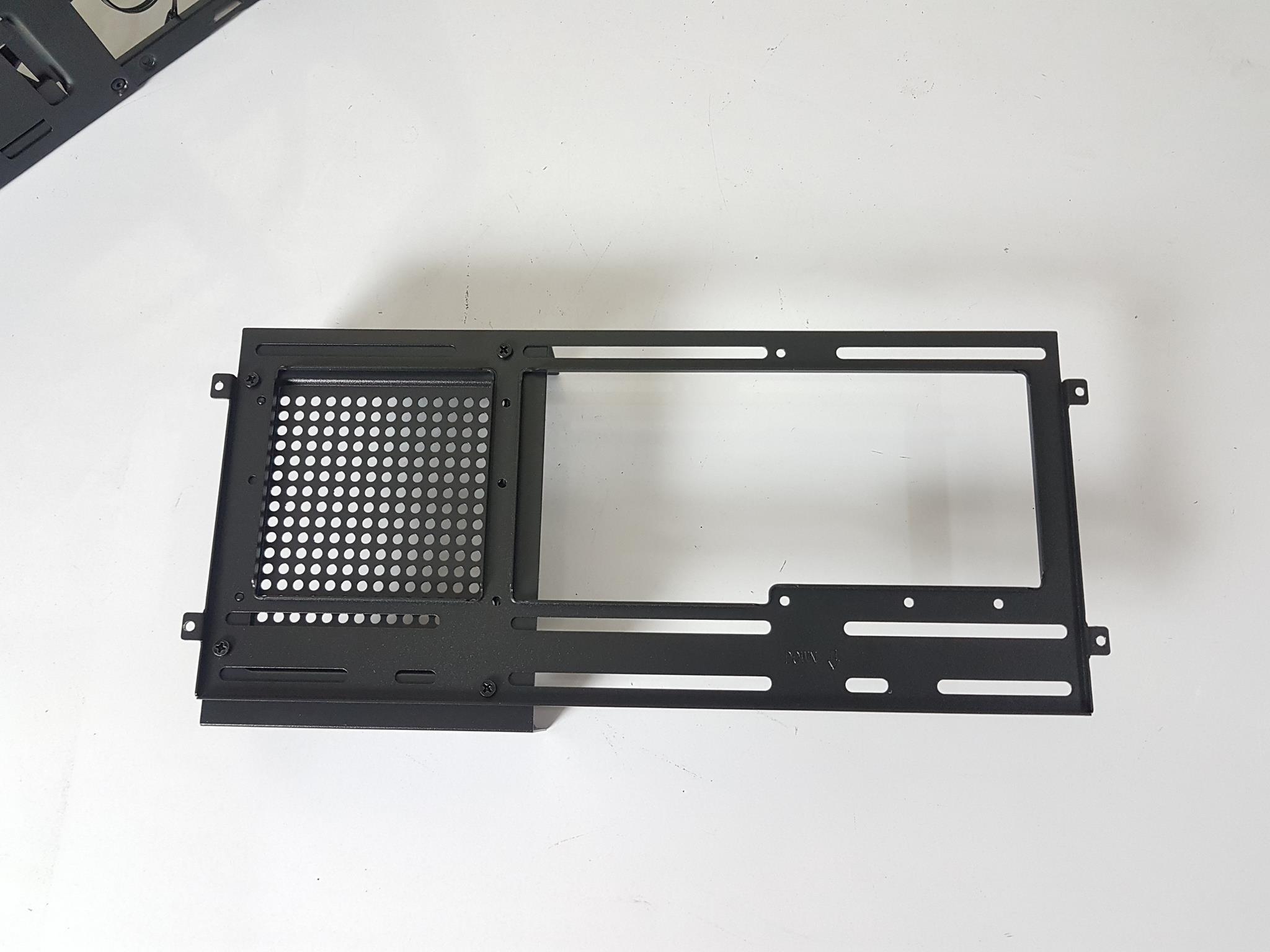
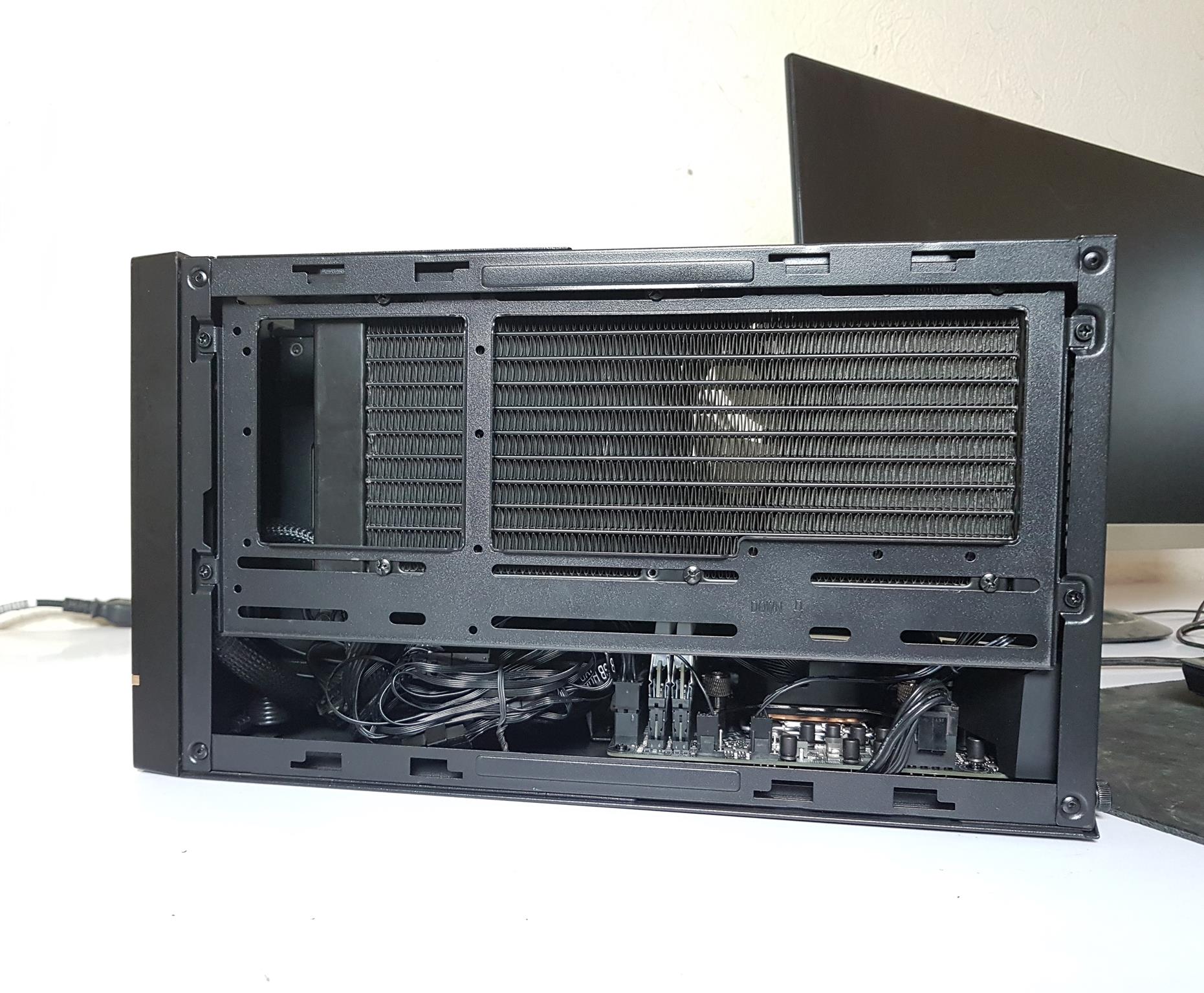
Now, we are left with one side of the chassis to cover. There is a mounting bracket or rail which is installed more towards the upper portion making enough room on the lower side. This is a smart design as we will need to deal with the cables when installing a 240mm AIO cooler. If you are wondering about the provision of the 3.5” and 5.25” drives mounting then your suspense is being suspended here as these drives are to be installed on this mounting bracket depending upon the configuration.
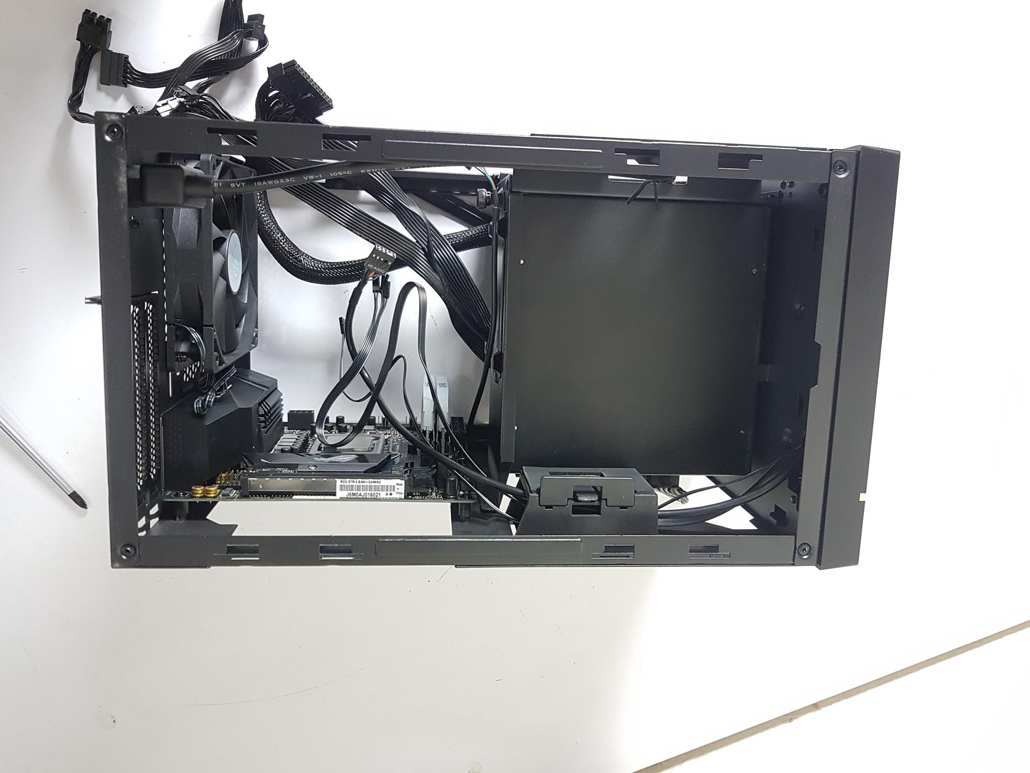
I am showing the above picture to give an idea about the overall layout with the bracket removed and components installed. Look at the cable clutter on the left side. All this needs to be managed before the installation of 240mm AIO on the bracket.
The mounting rail has 5.25” drive bracket pre-installed on it. Install your 5.25” drive on the bracket (located on the left side). The user can install 1x 5.25” drive.
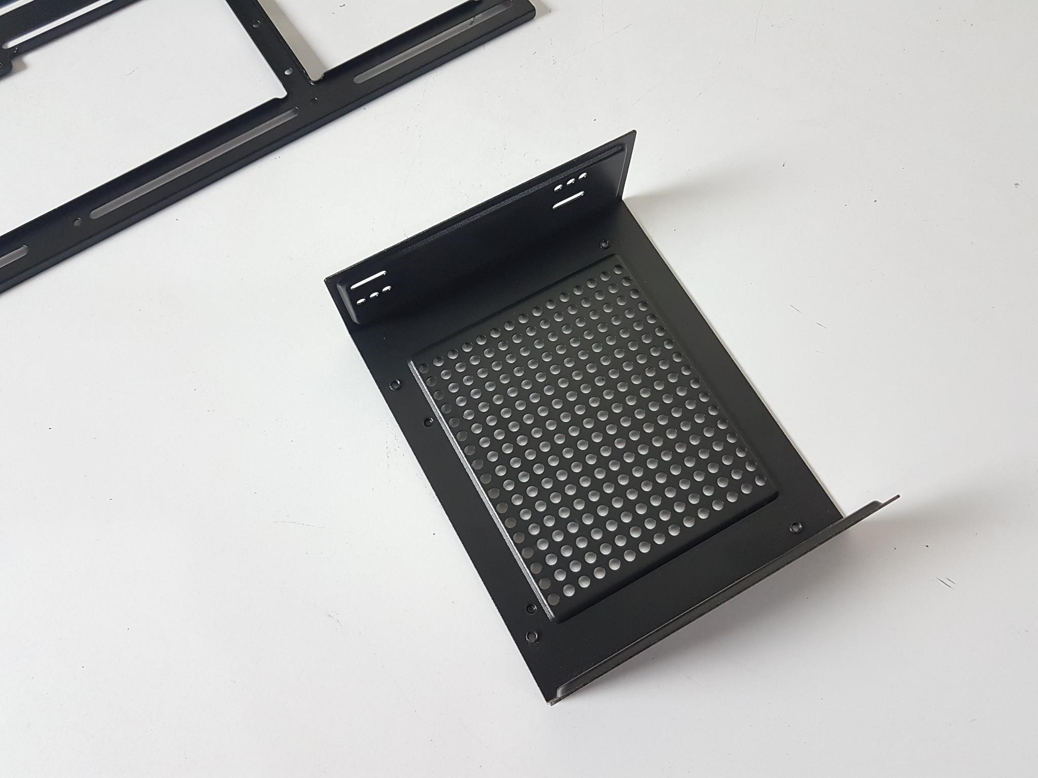
The above picture shows the 5.25” drive bracket. It is removed from the mounting rail/bracket. There are cutouts on the sides to secure install the 5.25” drive on this bracket.
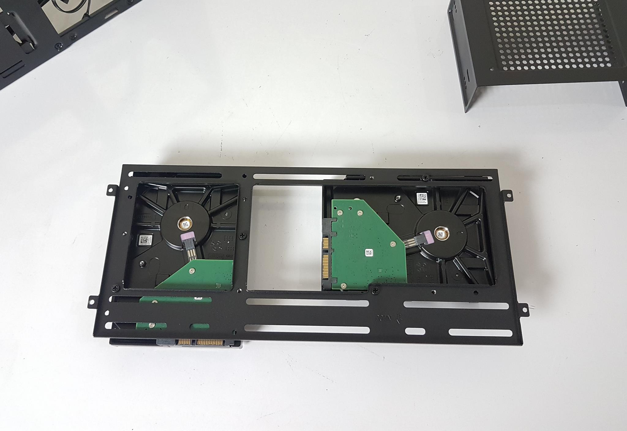
By removing the 5.25” bracket, the user can install up to 2x 3.5” drives as shown in the picture.
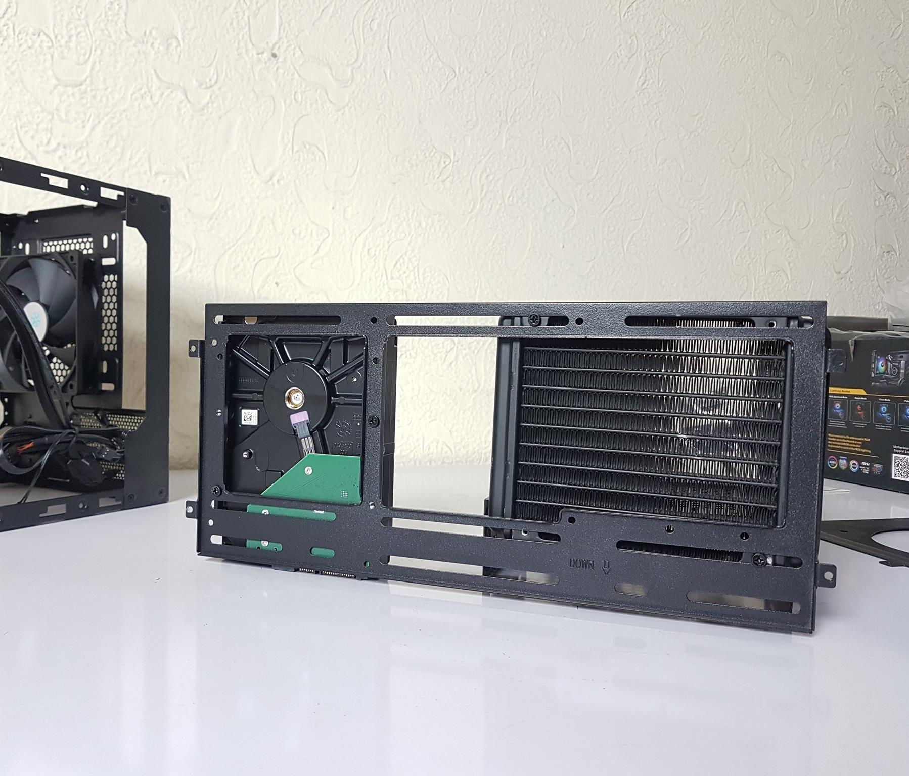
By removing the 5.25” bracket, the user can install 1x 3.5” drive and a 120mm AIO as shown in the picture. 120mm AIO can also be installed on the rear of the chassis. 140mm AIO is not supported anywhere in the chassis.
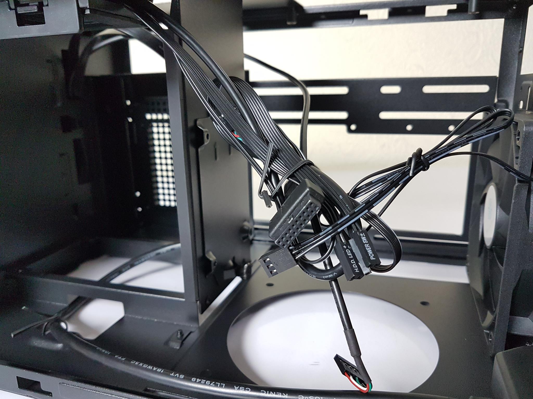
The IO Panel cables include:
- USB 3.0 cable
- USB 2.0 cable
- HD Audio cable
- Front Panel cables
Configurations
Before we move on to the build experience in the SUGO 14, let’s discuss the various installation configurations.
Configuration 1
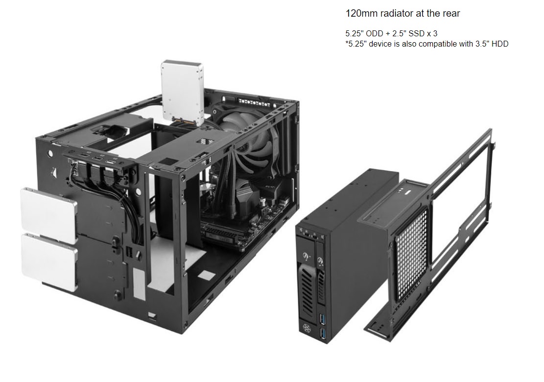
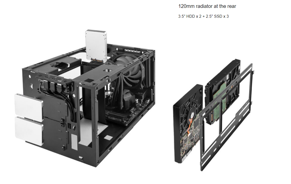
In this configuration the user can install 1x 120mm AIO on the rear and 3x 2.5” drives on the brackets. A 5.25” drive is also possible though installing a 3.5” is not possible. Alternatively, the user can replace the 5.25” drive with a 3.5” drive. The water block’s limitation is 55mm.
Configuration 2
In this configuration the user can install 1x 120mm AIO on the rear. By removing the 5.25” bracket, the user can now install 2x 3.5” drives. The user can still install 3x 2.5” drives.
Configuration 3
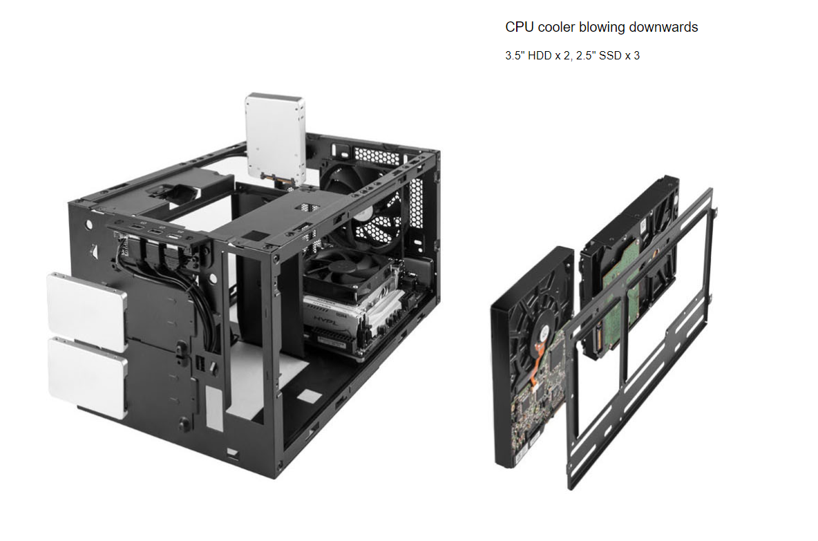
This configuration is similar to the Configuration 2 with one change. In this configuration we have removed the 120mm AIO cooler and replaced it with the low profile cooler blowing the air down.
Configuration 4
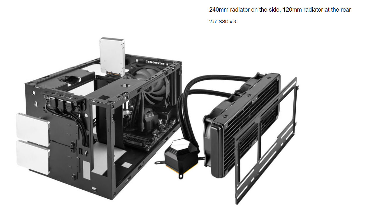
In this configuration, we are compromising on the 3.5” drives by installing a 240mm AIO on the side and a 120mm AIO on the rear. The user can still install up to 3x 2.5” drives. You can use this configuration with a water-cooled graphics card and water-cooled CPU.
Configuration 5
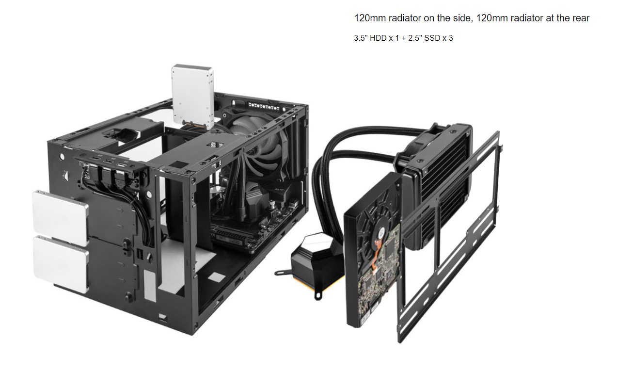
In this configuration the user can install 1x 3.5” HDD along with a 120mm AIO cooler on the side. This will also allow installation of a 120mm AIO on the rear. The user can still install 3x 2.5” drives.
Configuration 6
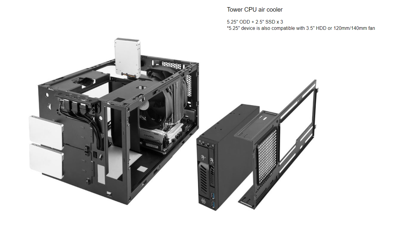
In this configuration, the user can install a tower CPU cooler. The maximum height allows for this type of cooler is 182mm without the top fan bracket. The user can still install 3x 2.5” drives. The user can install a 5.25” drive or 3.5” drive or a 120/140mm fan on the 5.25” drive bracket.
Test Build
Following test build has been used:
- Intel i9 9900k
- Asus ROG Strix B360-I (Z390 in ITX size are aliens in this market)
- Noctua NH-U12S
- CORSAIR H100i RGB Platinum
- XPG Spectrix D41 2x8GB @ 2667MHz
- Nvidia GeForce GTX 1080 FE
- HyperX 120GB SSD
- Cooler Master MWE 650W Gold PSU
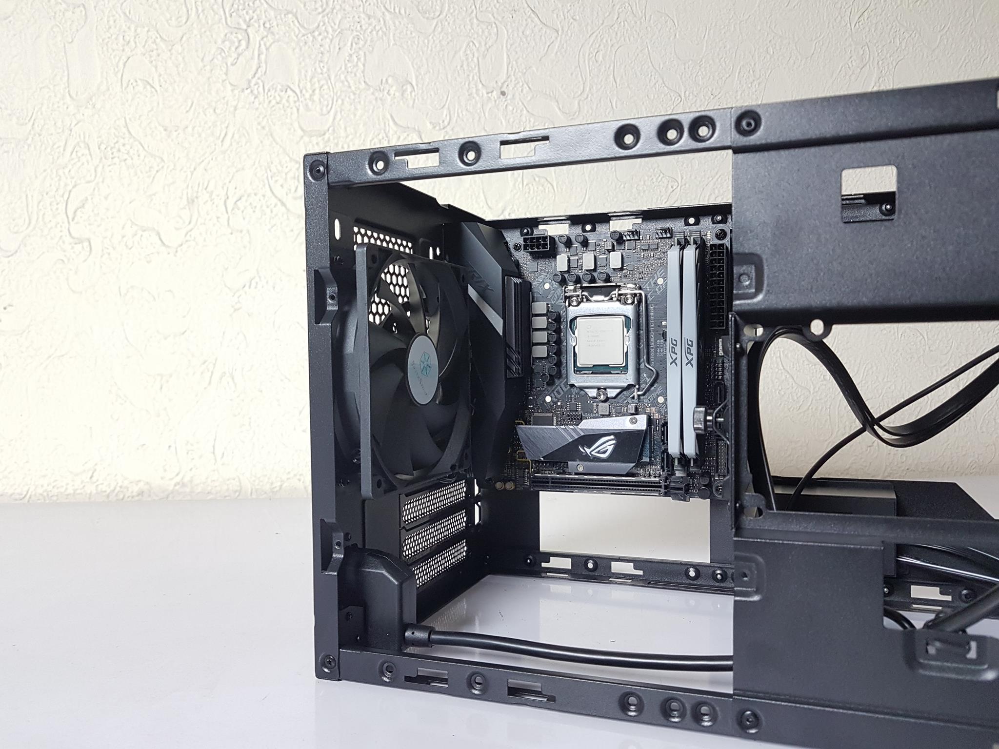
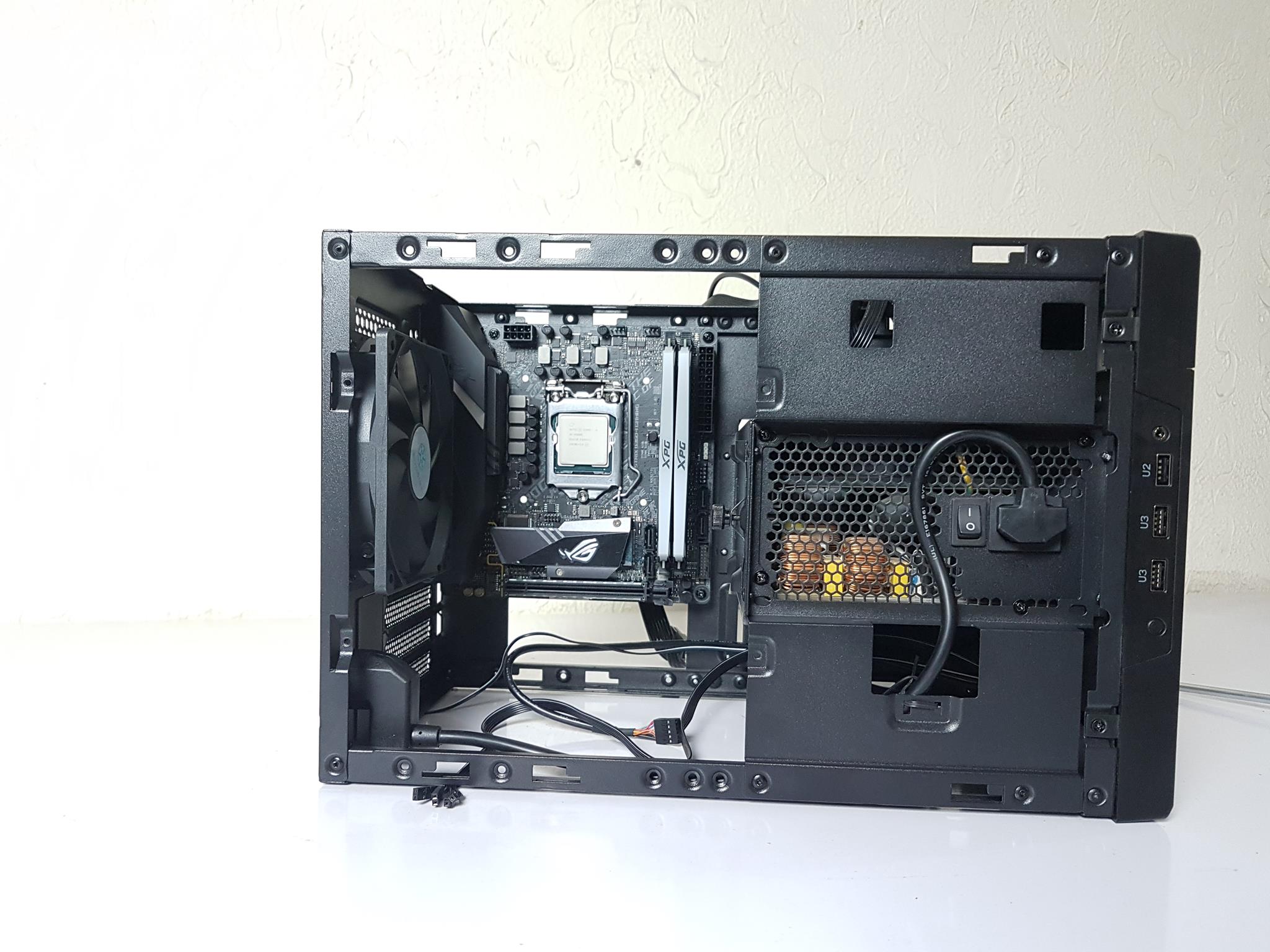
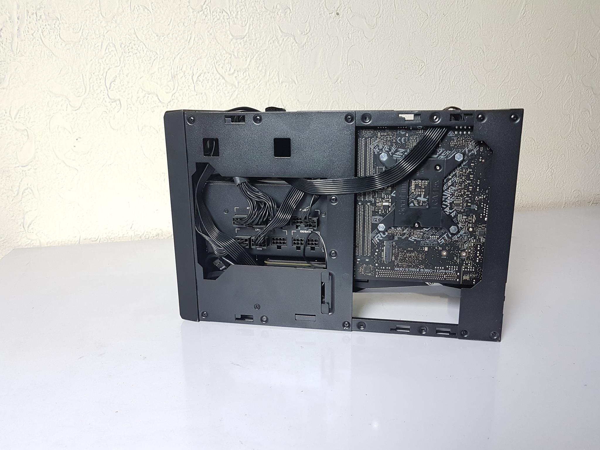
I started with installing the motherboard first. It made me realized that there is an ample space behind the motherboard that I could route the flat EPS cable from under the motherboard for better cable management.
This is another angle after the installation of the motherboard.
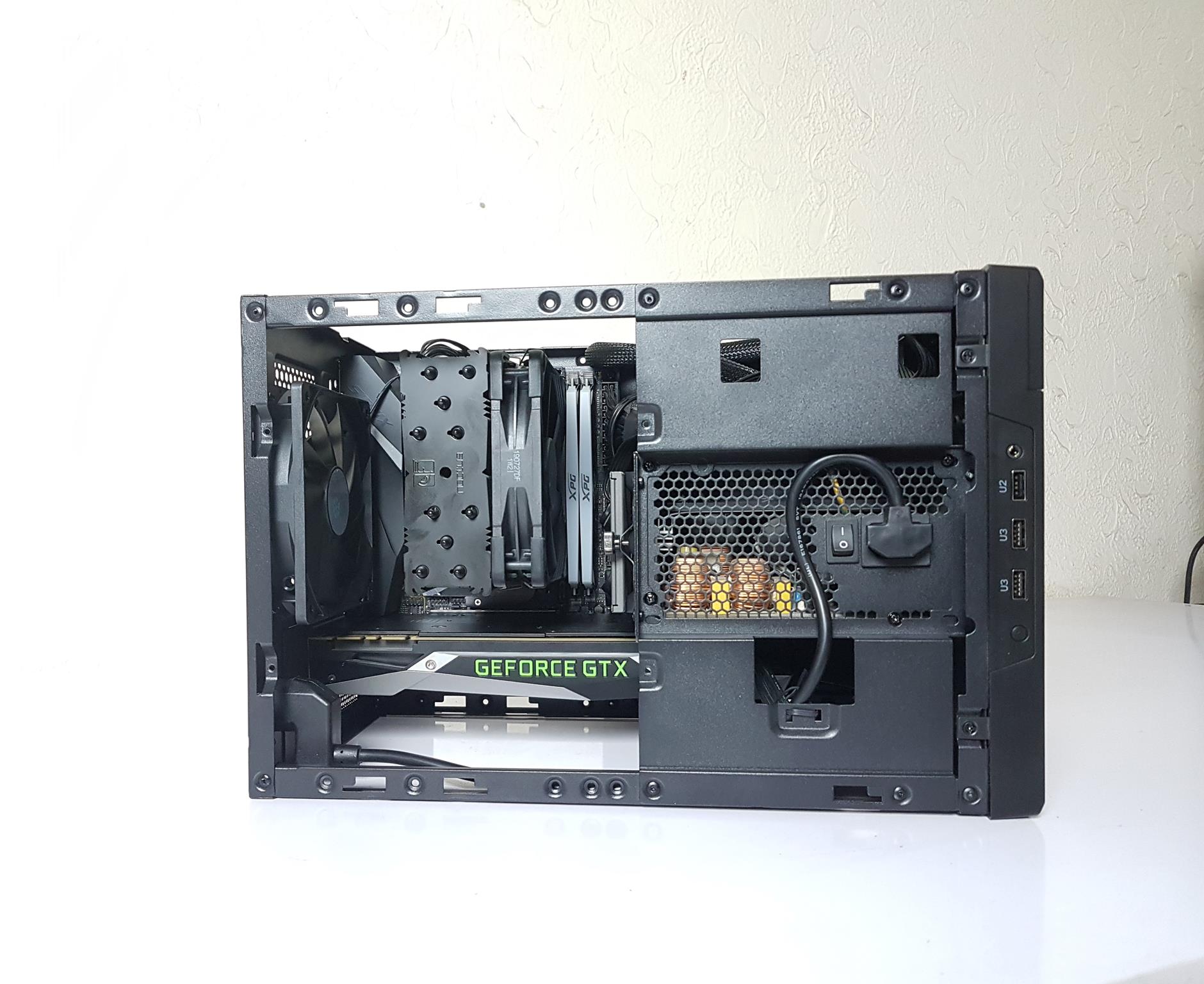
PSU was slided through its dedicated channel and secured using 4x screws. Make sure to power on the PSU power button otherwise you will be opening the side panel soon to power it on. I would love to see a power on/off button on the rear side of the chassis as well. The already routed power cord is not obstructing anything and so far the build experience has been good.
Since I have used a fully modular PSU, it was a blessing to have used only what cables were needed. The above picture is showing the cables without any management.
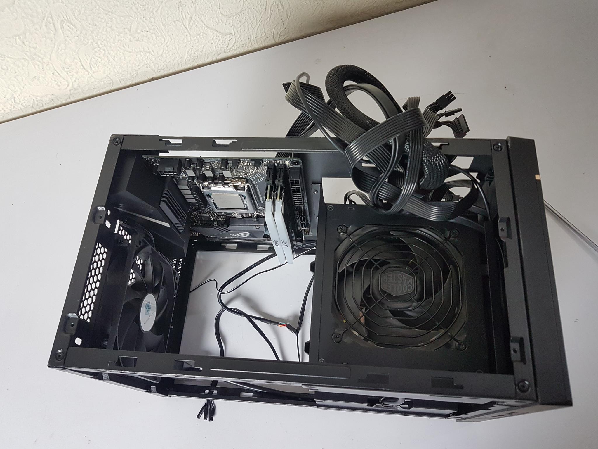
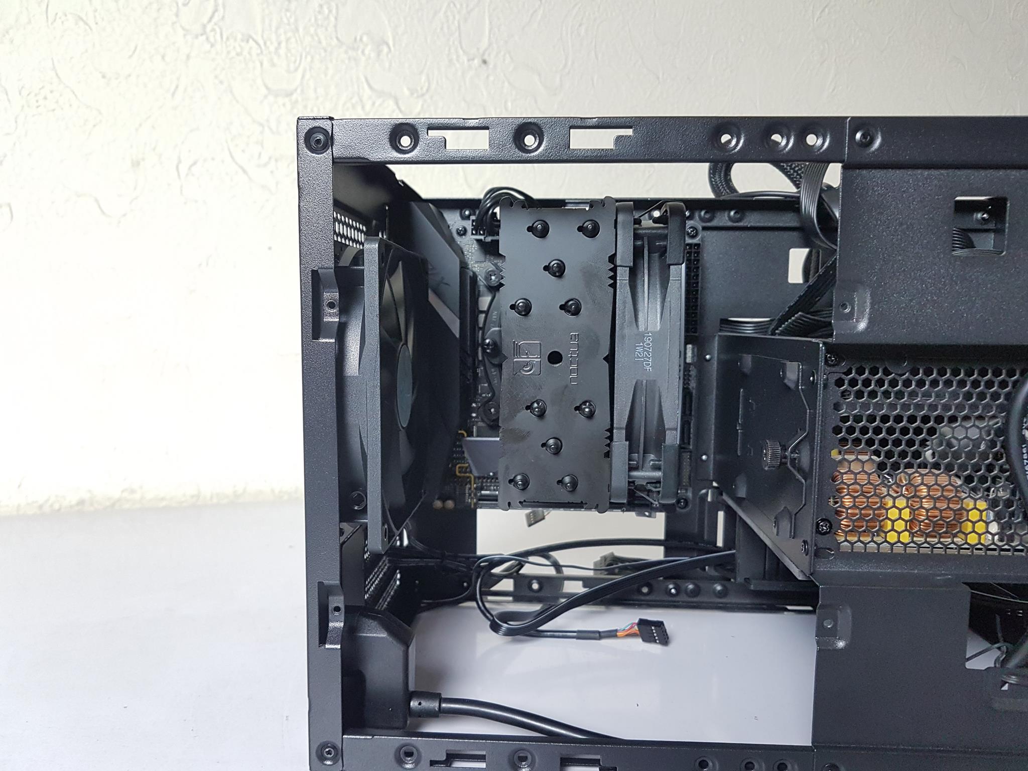
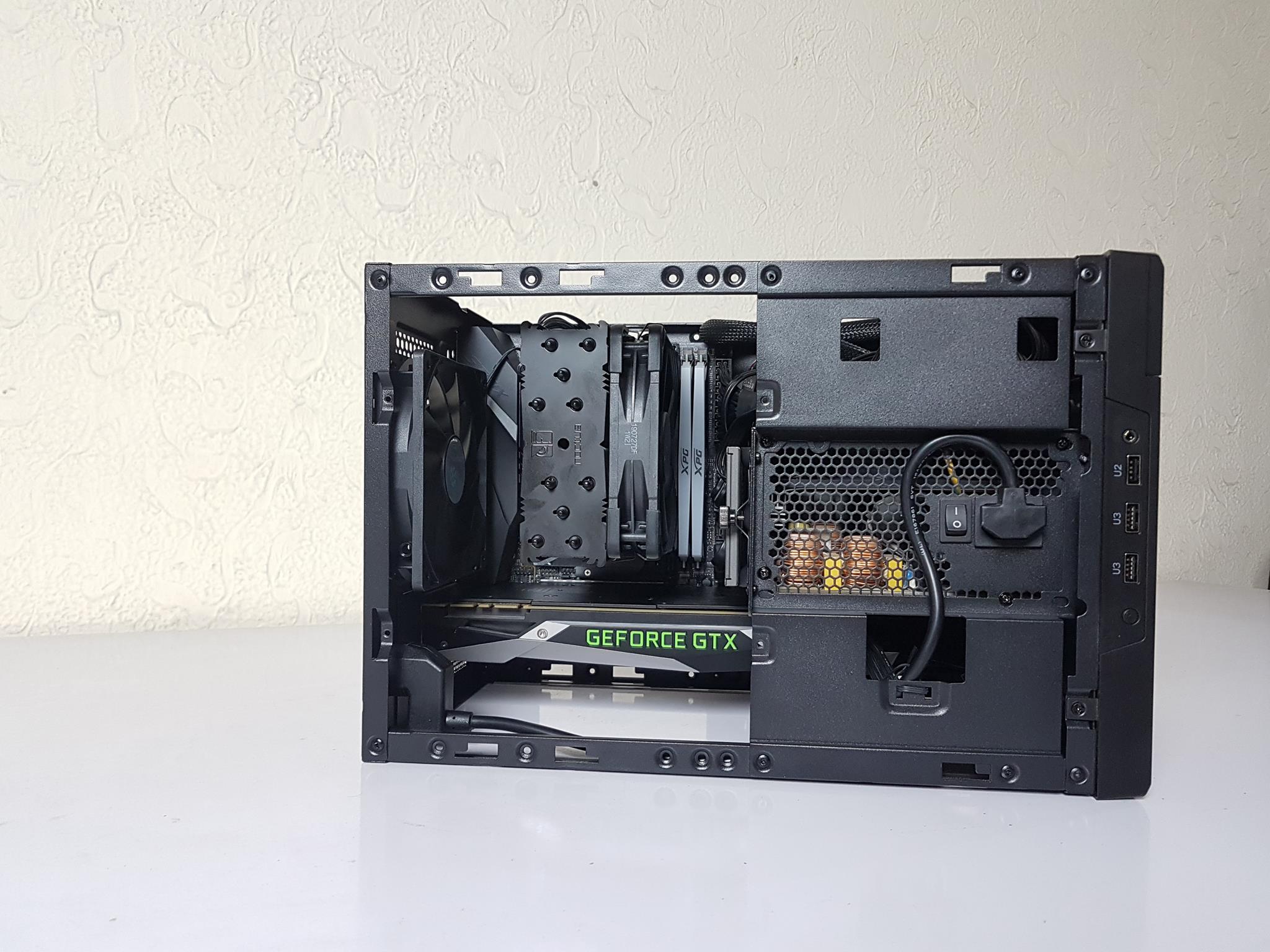
This is how it will look after the installation of the motherboard and the PSU. The user can install the CPU Cooler outside of the chassis as well as inside the chassis. I did not face any issues doing it inside the chassis.
The top view of the build so far. You would need to spend some time with the chassis to understand the flow of the layout and your required configuration and its layout. I would suggest installing the system panel cables before installing the CPU cooler and the SSD as with more components installed, the space would become restricted.
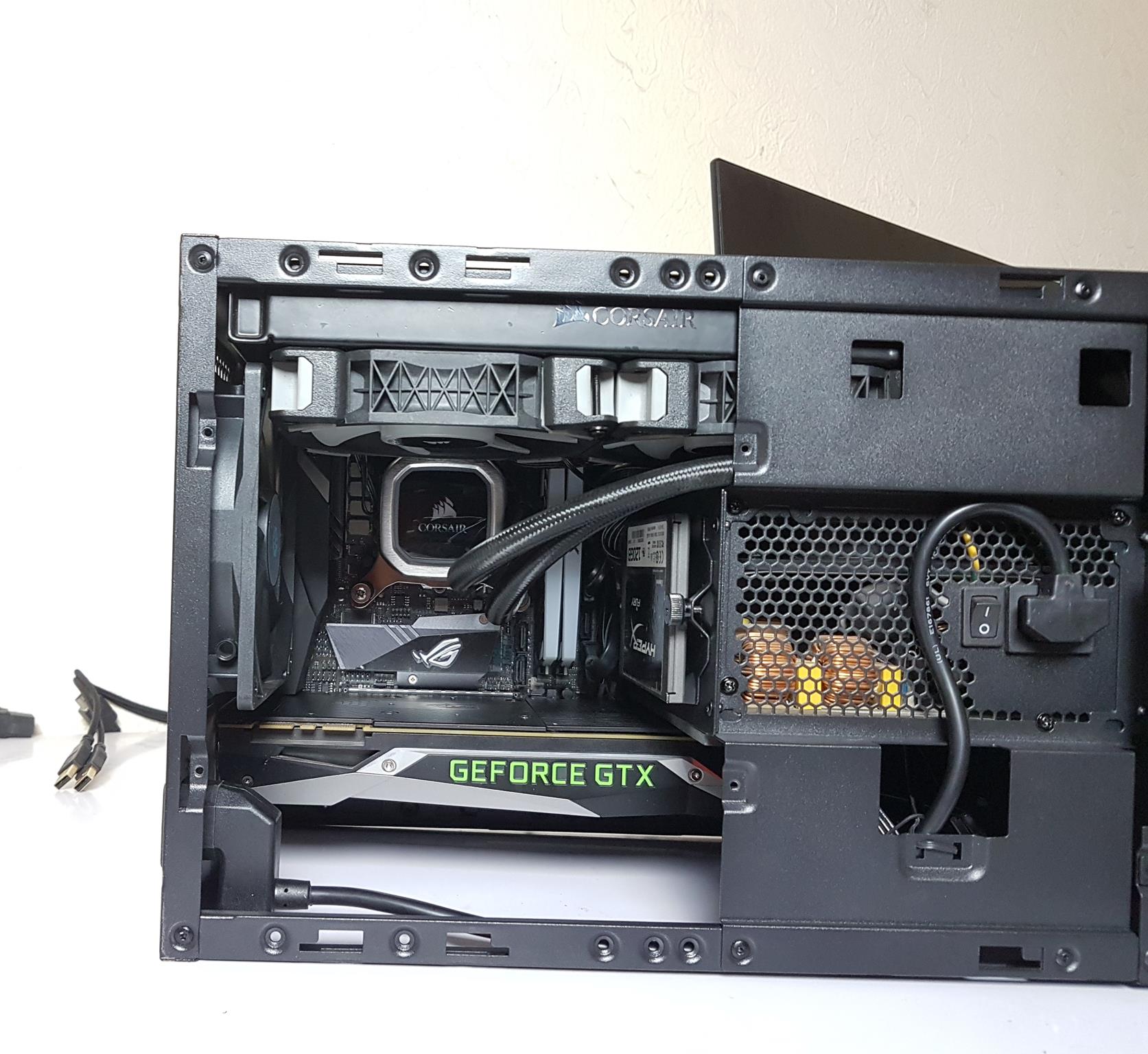
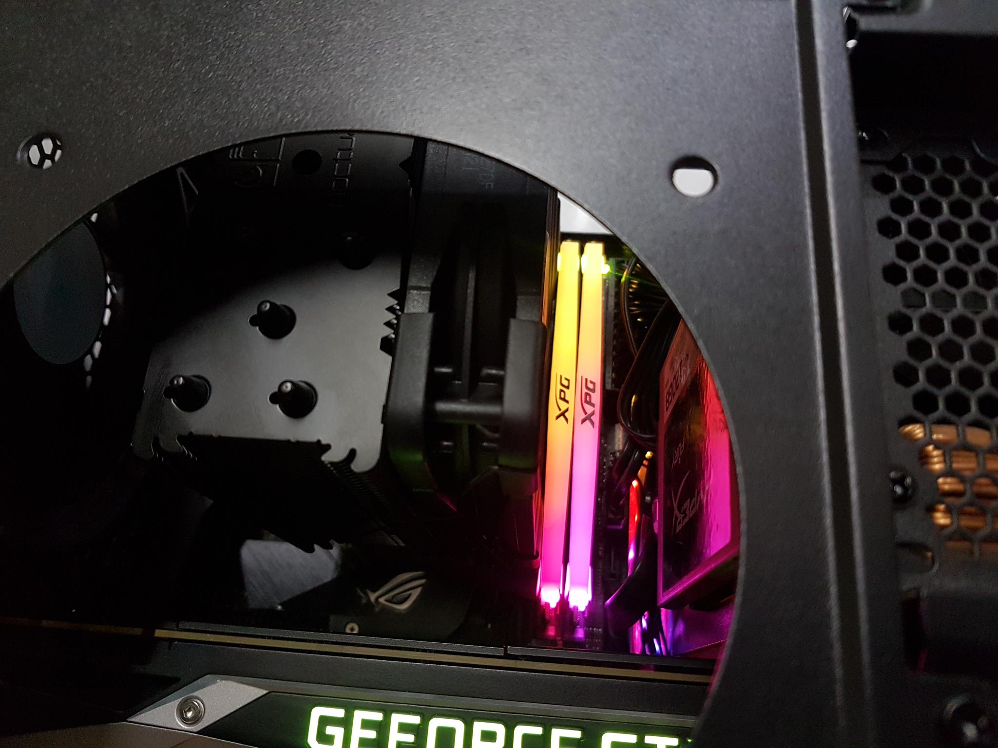
The CPU air cooler has been installed.
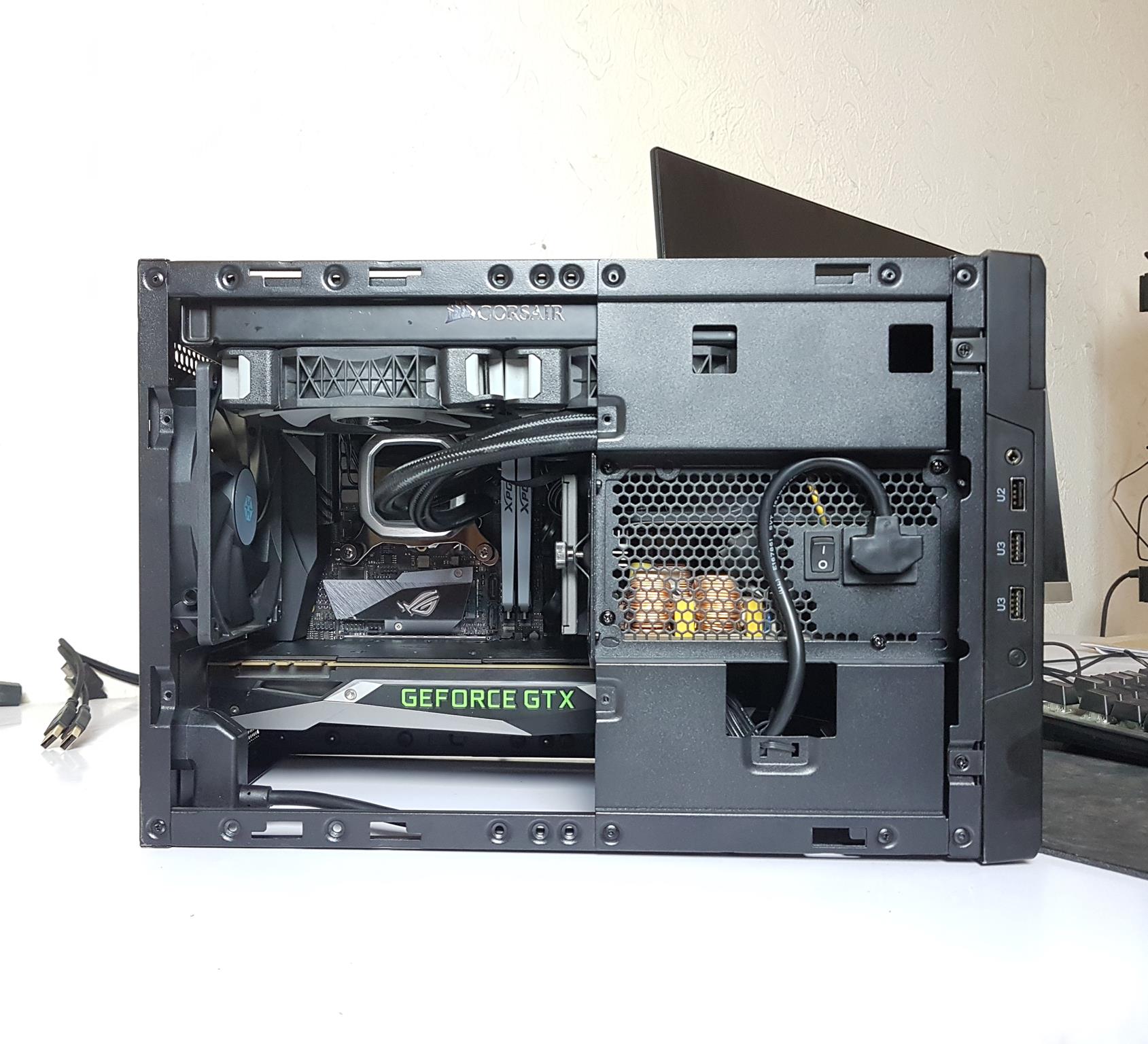
Almost there! The CPU Cooler, SSD and the graphics card have been installed. The layout is looking good.
The above picture is showing the backside with the cables installed and routed. Notice the routing of the EPS cable. This side has a solid steel side panel.
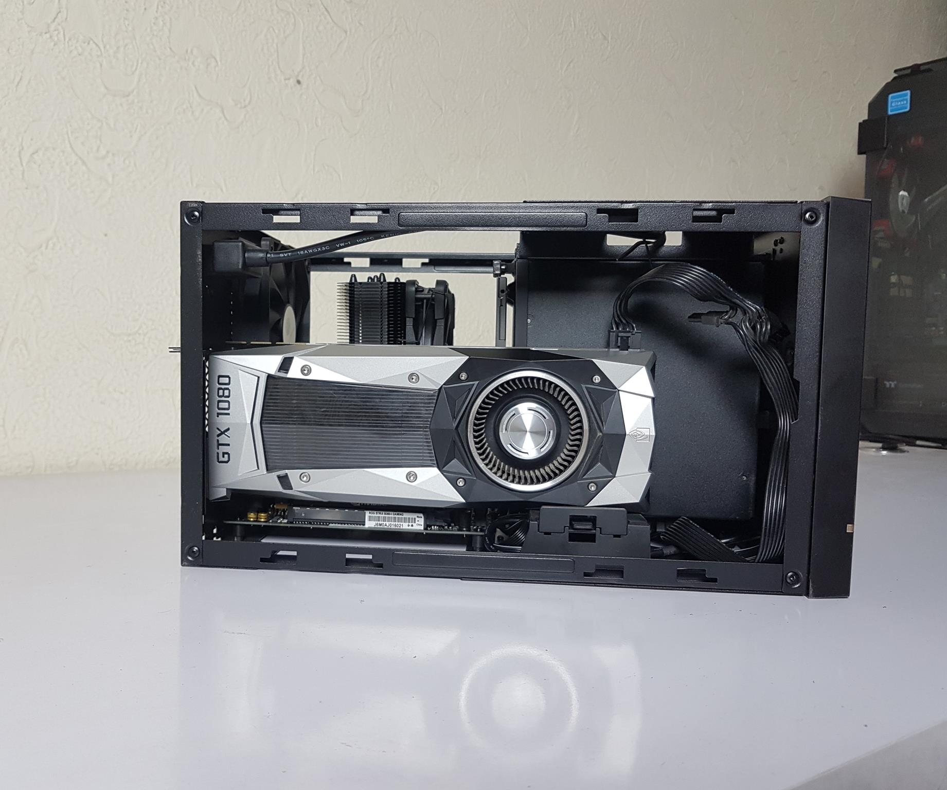
The graphics card is installed and the PEG cable is connected. The PEG cable was needed to be routed towards the back which is an easy task.
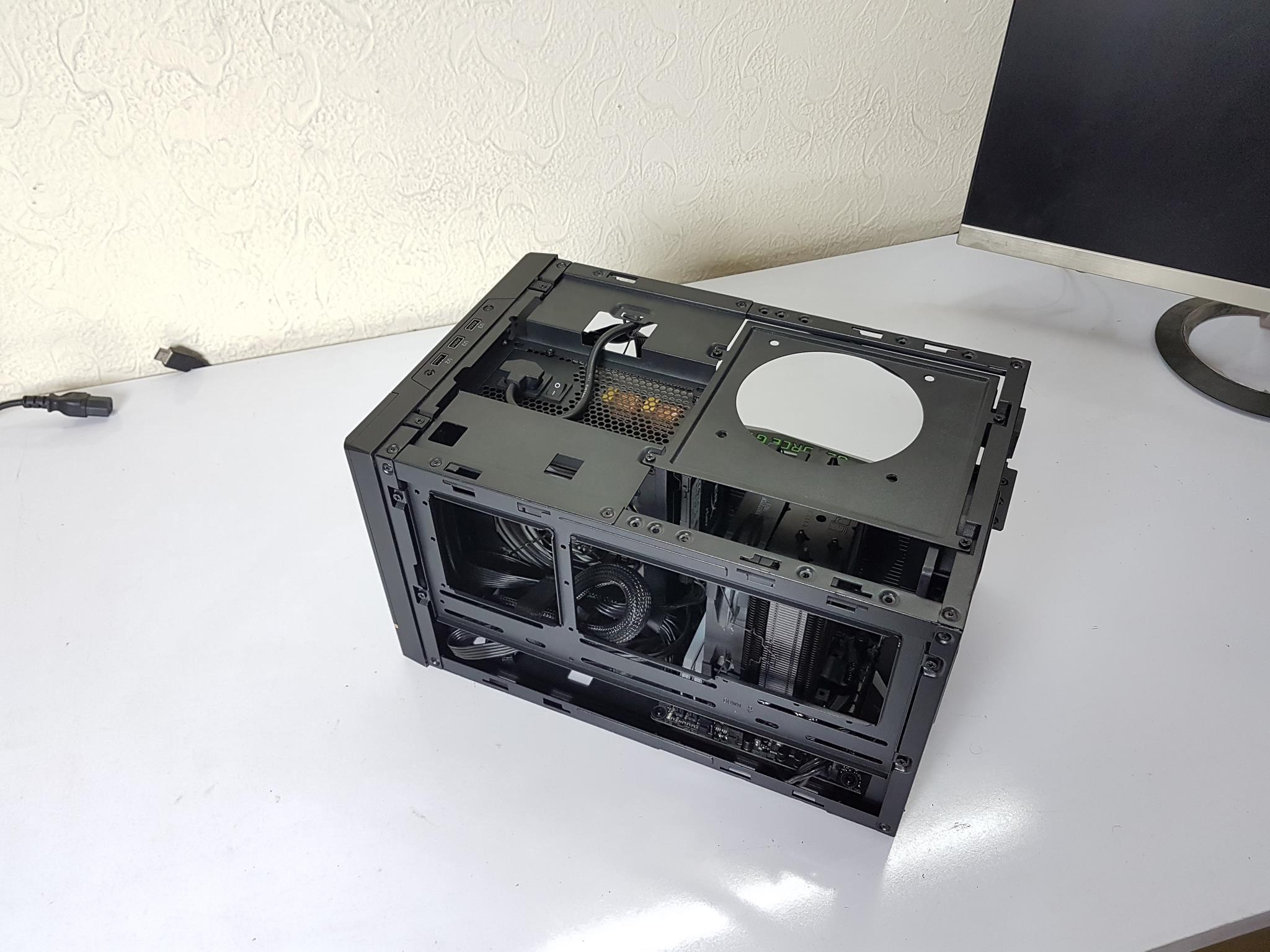
The fan bracket on the top and the side bracket is installed.
Another view of the build.
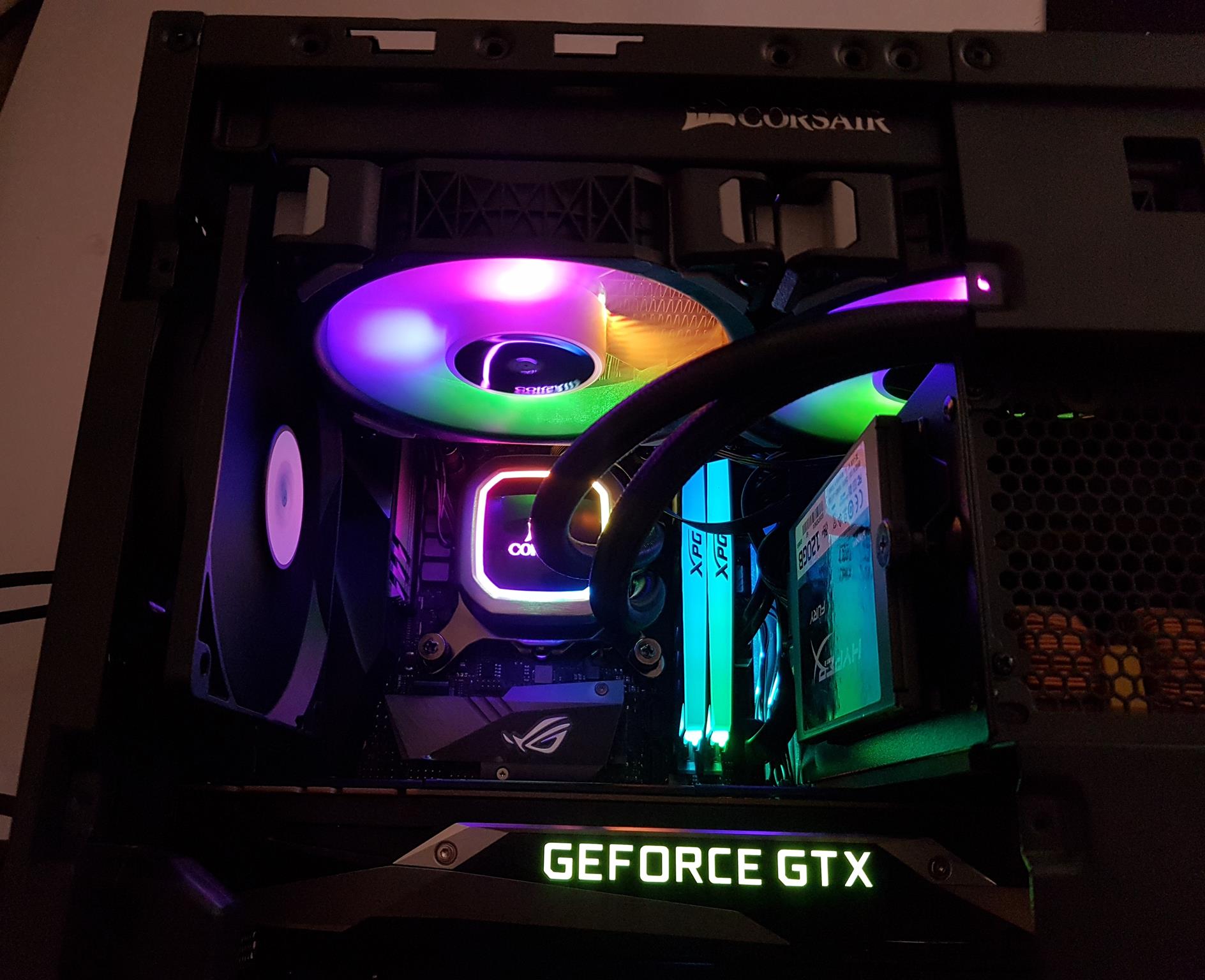
After the thermal performance was concluded with the air cooler, it was a time to install the 240mm AIO. Remember by this time the complete PC was assembled. I had to remove the tower cooler and install the 240mm AIO. All that was needed was to better manage the cables on the front of the PSU and tuck them towards the bottom area to make room for fans installed radiator assembly. Roughly 55mm of clearance is needed for the complete assembly.
The picture showing the radiator installed on the side bracket and the side bracket is installed on the chassis.
The picture is showing the front side of the build with AIO installed. You would need to be careful routing the tubes of the liquid cooler and un-obstructive passage for the fans. No cable should be hindering the fans.
The closed up view of the build.
Limitations/Restrictions
Following limitations/restrictions have to be kept in mind:
- The cooler height limit is 182mm, cooler is allowed to protrude to the edge of the motherboard by 6mm. If the top fan bracket is installed and no fan is installed on it, the height limit of the cooler is 174mm. If the upper fan bracket and fan are installed, the height limit of the cooler is 174 minus the thickness of the fan. For example 174-25=149mm would be the permissible height of the cooler with 25mm fan on the top.
- When using a tower cooler, no parts can be installed behind the right side bracket.
- When installing a 140mm fan or radiator on the rear half of the right side bracket, the CPU water block/air cooler height limit is 35mm. The Radiator thickness cannot be greater than 140mm.
- When installing 120mm fan or radiator on the rear half of the right side bracket, CPU water block / air cooler height limit is 55mm. Radiator thickness cannot be greater than 120mm.
- When installing the 3.5″ HDD rear half of the bracket, the CPU water block/air cooler height limit is 67mm.
- Maximum PSU depth is 160mm though 150mm is recommended.
- SUGO 14 can install graphics cards up to 330mm in length, and up to 148mm in width (Graphics card connector space does not affect the width limitation)
- In terms of PCB thickness, the rear of the graphics card is limited to 5mm at most and the front 60mm.
- If the CPU is installed with a 240mm liquid coolers, and the graphics card is air-cooled, a 120mm fan can be installed on the top fan bracket (pushing air outwards) to assist the graphics card’s heat dissipation.
- The fan of the PSU should be facing the right side
- If using tower air coolers, SilverStone recommends installing it with the fan blowing to the rear.
Thermal Performance
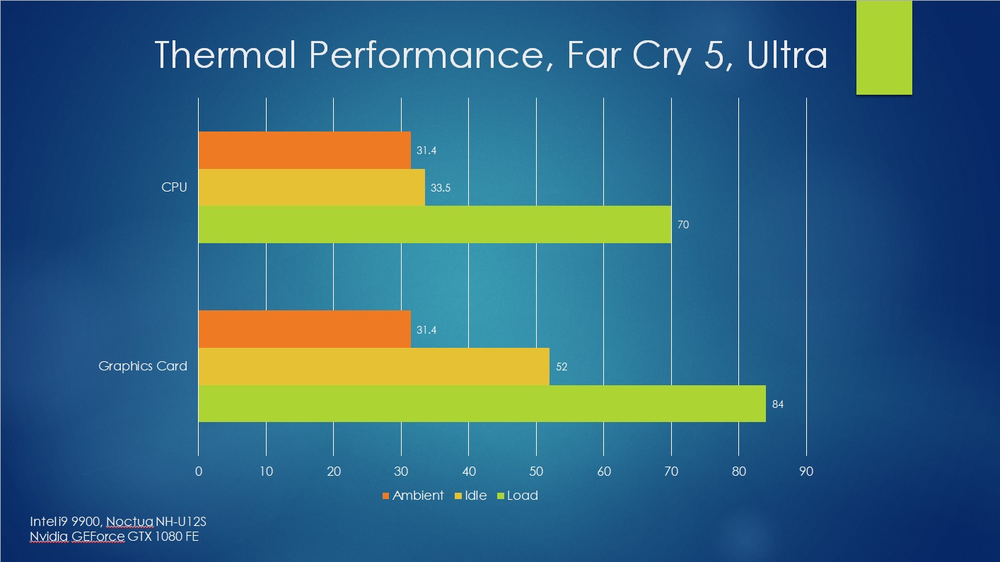
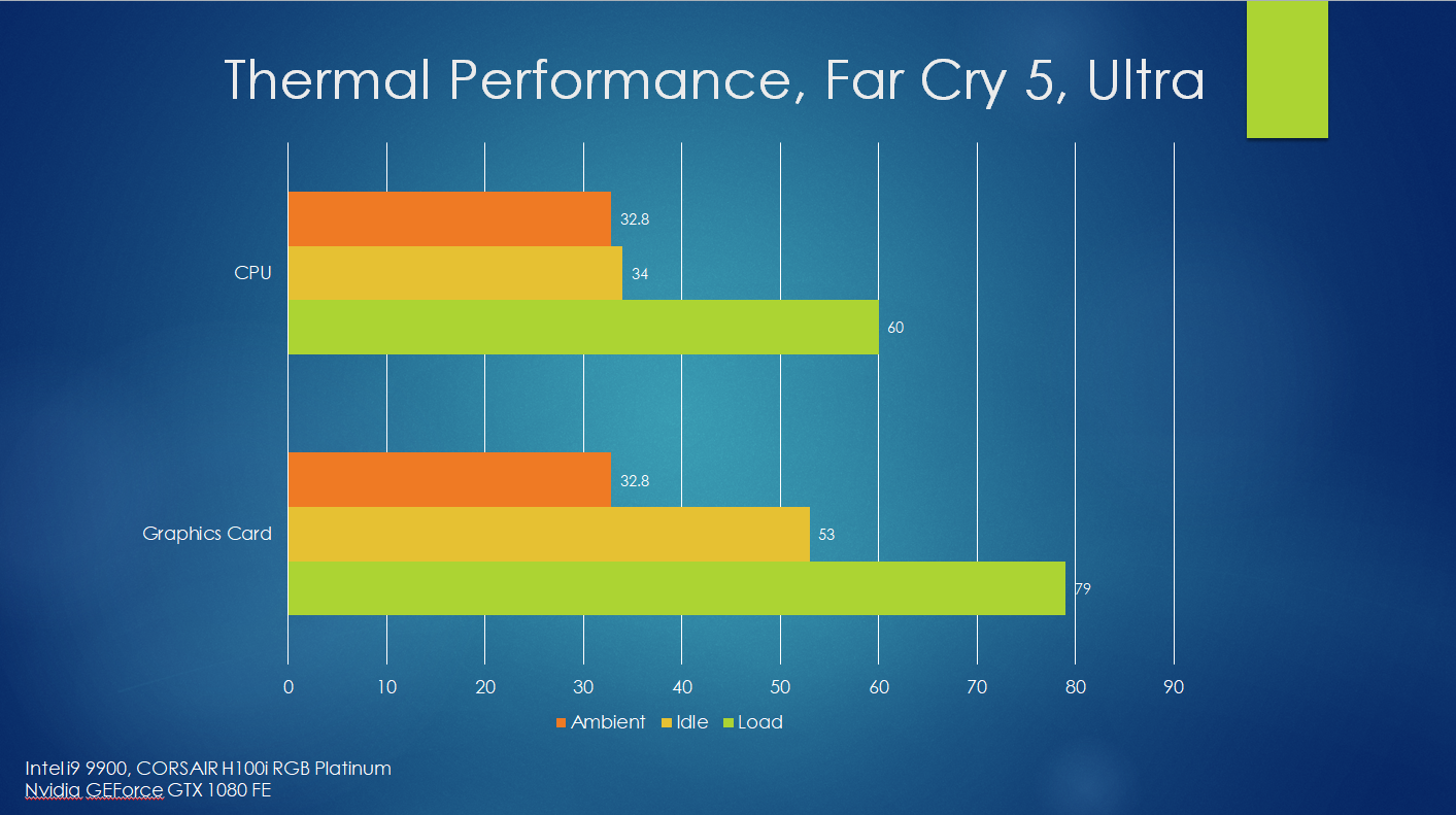
I have used Far Cry 5 at 1080p using Ultra settings for the gaming performance as the majority of the users would be gaming. The CPU was on stock settings with Asus Auto Enhancement disabled. I am not lucky with silicon on Intel i9 9900k as it runs hot out of the box.
The gaming temps are fine here. The reference cooler on GEForce GTX 1080 is struggling. A non reference cooler would have better indicated the thermal performance.
We can see the improvement in the temperatures with CPU on liquid cooler.
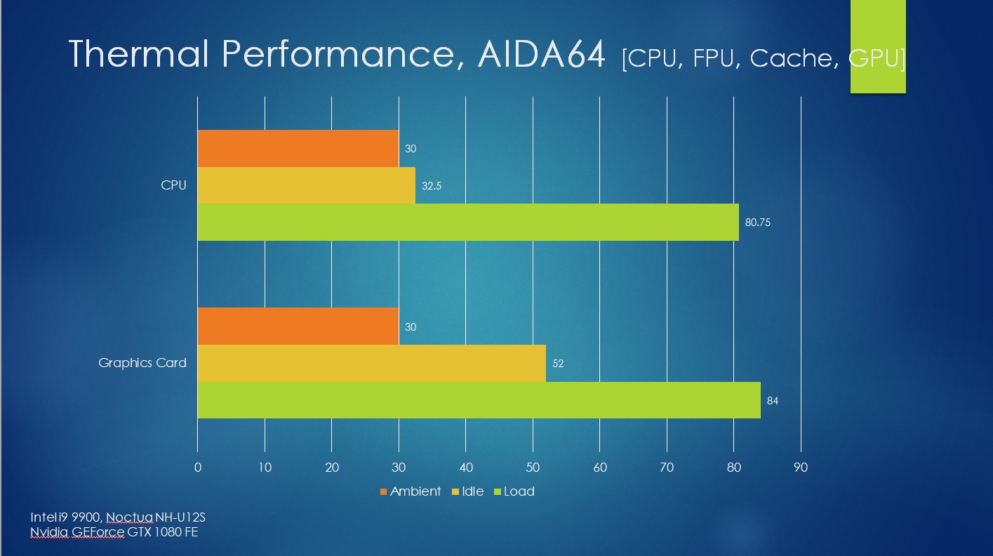
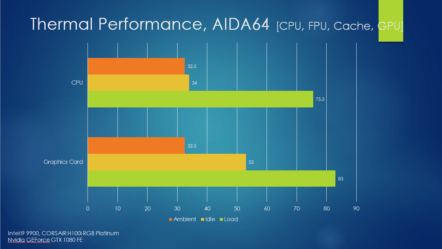
Next, the stress test was done using AIDA64 Extreme.
These are good temp under synthetic load in a SFF chassis. We are hitting thermal limit on GEForce GTX 1080 thanks to its struggling reference cooler.
The liquid cooler says it all. The CPU temperature has improved.
Conclusion
SilverStone has released new iteration in SUGO line up of their chassis named SUGO 14. It has come with some fine refinements that would interest many as this is a feature-rich ITX cube chassis. The SUGO 14 has a dimension of 247x215x368.1mm (WxHxD) with 19.55 liters. The chassis is made of steel with front panel made of plastic. The cube design has 4x steel made panels. Three side panels have magnetic dust filters on the perforated portion. One side panel is solid made without any perforation. The front panel is configurable. The killer features highlight is:
- Mini-ITX and Mini-DTX compatible.
- Mini-ITX cube chassis with configurable front panel
- Supports 3 slot full-length graphics cards with adjustable graphics card holder
- Standard PS2 ATX PSU
- Supports up to 240mm radiators
- Modular design with 4 removable panels (top, left, right, bottom)
Storage Options:
- Up to 3x 2.5” drives
- Up to 2x 3.5” drives
- Up to 1x 5.25” drive
The user can install 3x 2.5” drives at any time. The rest of the options are dependent on the configuration under consideration. There are 6 configuration possibilities with SUGO 14. For more details, check our Configurations section.
Cooling Provision:
- 1x 120/140mm fan on the rear [1x 120mm pre-installed]
- 1x 120mm fan provision on the top bracket [optional]
- 120mm AIO on the rear
- 120/240mm AIO on the side
The permissible height of the CPU air cooler is 182mm without a top bracket. The maximum length of the graphics card is 330mm with a width of 148mm as this chassis supports a triple slot. SilverStone has suggested using 150mm PSU though 160mm PSU can be installed. There is no SFF bracket provided as this chassis is designed around standard ATX PSU. There is a graphics cardholder as well. The backside of the chassis has enough clearance to install an M.2 SSD on the back of the motherboard.
Build experience inside the SUGO 14 is pleasing. We did not face any issue in this regard. Spending some time to familiarize yourself with the overall layout and knowing the restrictions and the configurations would help you in planning the build. The temperatures are a bit warm with air cooling which is understandable but we can manage them with a beefy cooler or liquid cooler. When using a liquid cooler on the CPU, one should consider installing a 120mm fan on the top bracket to help with the heat exhaust of the graphics card.
The SilverStone SUGO 14 is listed at $110 at the time of the review. With its expandability, modularity, and usability, the SUGO 14 has brought more features on the tables that are hard to find in the SFF market particularly a triple-slot design for the beefy graphics card, ability to use a combination of 120mm and 120/240mm AIOs, a full-size air cooler and standard ATX PSU makes this proposition outstanding and as such comes recommended by us.
We are thankful to SilverStone for providing a review sample of SUGO 14.


